//template
<Purpose- it should introduce what the blue print is about, industry, business use case, applications and where it sits on the edge infrastructure>
<It should be readable by a semi technical audience , e.g. product marketing, business account executives etc>
<use case 1>
<use case 2>
<use case 3>
Business Drivers
<This could inform the non-technical audience, but now is more geared towards a more engaged, technical audience>
< Blue print's relation to Akraino generic architecture, how it relates to it >
< This section will use the Akraino architecture document as reference>
<Hardware components should be specified with model numbers, part numbers etc>
<Software components with version/release numbers >
<EDGE Interface>
<ETSI MEC Interaction>
APIs with reference to Architecture and Modules
High Level definition of APIs are stated here, assuming Full definition APIs are in the API documentation
GNU/common license
The purpose of Public Cloud Edge Interface (PCEI) Blueprint family is to specify a set of open APIs for Telco Edge Blueprints to expose towards Public Cloud Service Provider instances at the Edge. As Public Cloud Service Providers deploy Edge instances to better serve their end users and applications, Telco Edge deployments offer many opportunities for collaboration by exposing their network capabilities to provide value added services.
Currently the challengers includes:
This BP family is trying to resolve these challengers for both telco and hyperscalers.
High level architectural view:
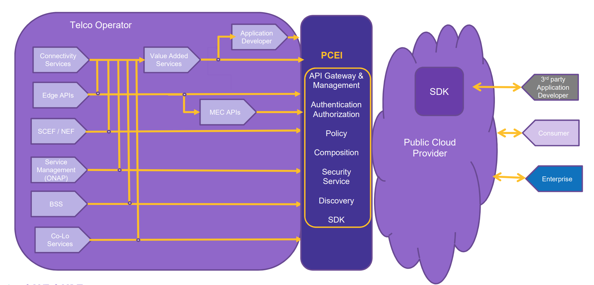
Architecture as following. This BP will bring a new "Enabler" layer as PCEI between the Telco network and public cloud platform on edge. The PCEI layer is responsible for :
In southbound, this layer will encapsulate the core network capabilities, interwork with BSS/OSS/management system from telco operators. We first suggest to deploy this layer on telco's edge hardware resource.
And in northbound, it provides RESTFUL APIs and SDKs to be called and integrated by public clouds.

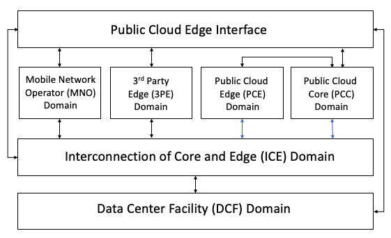
The PCEI Enabler is expected to provide Multi-Domain Interworking capabilities between the following domains:
The following figure shows high-level relationships between the domains:

The Data Center Facility (DCF) Domain. The DCF Domain includes Data Center physical facilities that provide the physical location and the power / space infrastructure for other domains and their respective functions.
The Interconnection of Core and Edge (ICE) Domain. The ICE Domain includes the physical and logical interconnection and networking capabilities that provide connectivity between other domains and their respective functions.
The Mobile Network Operator (MNO) Domain. The MNO Domain contains all Access and Core Network Functions necessary for signalling and user plane capabilities to allow for mobile device connectivity. These functions include the Radio Access Network (RAN), including the 5G New RAN (5GNR), Packet Core, including the Virtualized Evolved Packet Core (vEPC) and the 5G Core (5GC).
The Public Cloud Core (PCC) Domain. The PCC Domain includes all IaaS/PaaS functions that are provided by the Public Clouds to their customers. These include Virtual Private Cloud and Public/Private Networking capabilities.
The Public Cloud Edge (PCE) Domain. The PCE Domain includes the PCC Domain functions that are instantiated in the DCF Domain locations that are positioned closer (in terms of geographical proximity) to the functions of the MNO Domain. In general, the PCE functions are expected to be managed from the PCC functions.
The 3rd party Edge (3PE) Domain. The 3PE domain is in principle similar to the PCE Domain, with a distinction that the 3PE functions may be provided by 3rd parties (with respect to the MNOs and Public Clouds) as stand-alone instances of Edge Computing resources/applications.
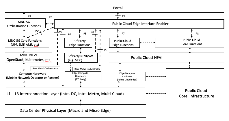
The PCEI Reference Architecture and the Interface Reference Points (IRP) are shown in the figure below. Note the this figure also provides a component layer view of the PCEI Architecture:

The PCEI Reference Architecture layers are described below:
The PCEI Data Center (DC) Physical Layer belongs to the DCF Domain and provides the physical DC infrastructure located in appropriate geographies (e.g. Metropolitan Areas). It is assumed that the Public Cloud Core infrastructure is interfaced to the PCEI DC Physical Layer through the PCEI L1-L3 Interconnection layer.
The PCEI L1-L3 Interconnection Layer belongs to the ICE Domain and provides physical and logical interconnection and networking functions to all other components of the PCEI architecture.
Within the MNO Domain, the PCEI Reference Architecture includes the following layers:
Within the Public Cloud Domain, the PCEI Reference Architecture includes the following layers:
Within the 3rd Party Edge Domain, the PCEI Reference Architecture includes the following layers:
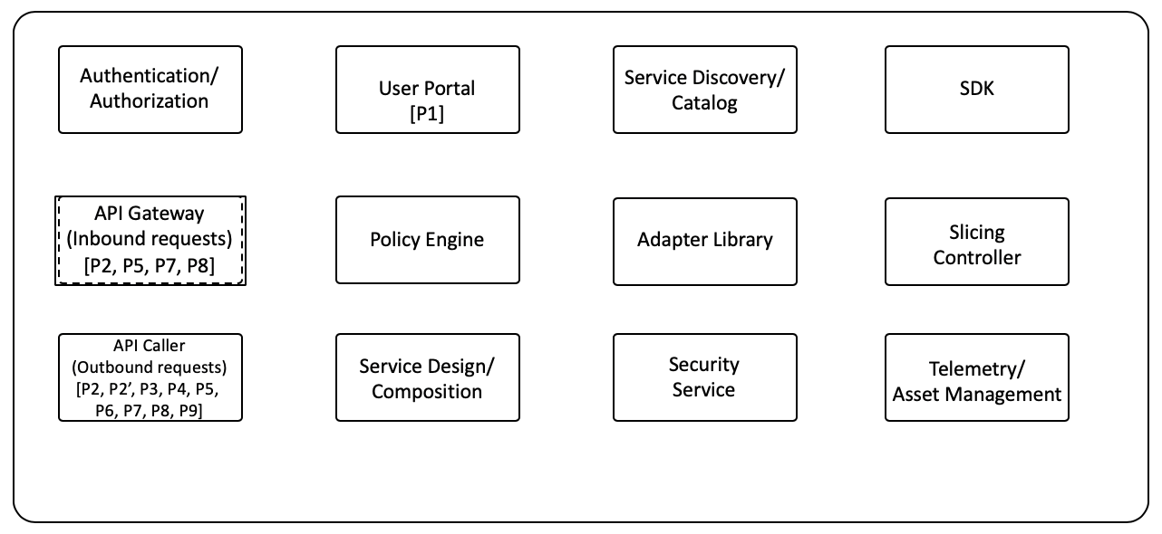
The PCEI Enabler. A set of functions that facilitate the interworking between PCEI Architecture Domains. The structure of the PCEI Enabler is described later in this document.
The PCEI Portal. An optional component of the PCEI Architecture responsible for providing the users of PCEI a way to express and communicate their intended functional, performance and service requirements.
P1 – User Intent. Provides ability for User/Customer to specify PCEI access and functional requirements E.g. Type of Access, Performance, Connectivity, Location, Topology
P2 – Interface between PCEI and Mobile Network. Provides ability to accept requests from MNO for PCEI service and request MNO to provide 4G/5G access to PCEI customers. E.g. Network Slicing, LBO.
P2' - Interface between PCEI and the MNO Core Functions such as UPF, SMF. In case of a UPF the P2' interface can be used to configure the parameters responsible for interfacing the UPF and the virtual/contextual configuration structures within the UPF with the PCC/PCE and 3PE resources by way of the L1-L3 Interconnection layer. The P2' interface implies the availability of standard or well specified UPF provisioning models provided by MNOs.
P3 – Interface between PCEI and Compute Hardware Orchestrator for distributed MNO functions (e.g. non-MNO locations). Provides ability for PCEI to trigger orchestration of appropriate HW resources for MNO User Plane and other appropriate functions. May be triggered through P2 by MNO
P4 – Interface between PCEI and Interconnection Fabric. Provides ability to request and orchestrate network connectivity and performance KPIs between MNO UPF, Cloud Core and Edge resources (including 3rd Party Edge)
P5 – Interface between PCEI and 3rd Party Edge Functions (e.g. NFV). Provides ability to access Edge APIs exposed by 3rd Party Edge Functions (e.g. deployment of NFVs and Edge Processing workloads)
P6 – Interface between PCEI and Edge Compute Hardware Orchestrator. Provides ability for PCEI to trigger orchestration of appropriate HW resources for Edge Compute functions including Public Cloud Edge and 3rd party Edge.
P7 – Interface between PCEI and Public Cloud Edge Functions (may be part of P8). Provides ability to access APIs to deploy Public Cloud Edge functions/Instances (may be done through P8)
P8 - Interface between PCEI and Public Cloud Core Functions (may include control over Public Cloud Edge functions). Provides ability to access Public Cloud APIs including ability to deploy Public Cloud edge functions.
P9 - Interface between PCEI and the NFVI layer of the 3PE Domain. P9 may be used If a MNO chooses to expose the NFVI layer to PCEI.

provide an end to end deployment with this enable layer between telco and public cloud.
xxx