The 5th Generation of Mobile Networks (a.k.a. 5G) represents a dramatic technological inflection point where the cellular wireless network becomes capable of delivering significant improvements in capacity and performance, compared to the previous generations and specifically the most recent one – 4G LTE.
5G will provide significantly higher throughput than existing 4G networks. Currently 4G LTE is limited to around 150 Mbps. LTE Advanced increases the data rate to 300 Mbps and LTE Advanced Pro to 600Mbps-1 Gbps. The 5G downlink speeds can be up to 20 Gbps. 5G can use multiple spectrum options, including low band (sub 1 GHz, mid-band 1-6 GHz and mmWave 28, 39 GHz). The mmWave spectrum has the largest available contiguous bandwidth capacity (~1000 MHz) and promises dramatic increases in user data rates. 5G enables advanced air interface formats and transmission scheduling procedures that decrease access latency in the Radio Access Network by a factor of 10 compared to 4G LTE.
Network Slicing (NS) refers to the ability to provision and connect functions within a common physical network to provide resources necessary for delivering service functionality under specific performance (e.g. latency, throughput, capacity, reliability) and functional (e.g. security, applications/services) constraints.
It is important to point out that the keyword “network” refers to the complete system that provides services and not specifically to the transport and networking functions that are part of this system. In the mobile context, the examples of networks are the Evolved Packet System (EPS) delivering 4G services and the 5G System (5GS) delivering 5G services. Both systems include the RAN (LTE, 5GNR), Packet Core (EPC, 5GC) and transport/networking functions that can be used to construct network slices.
The technological capabilities defined by the standards organizations (e.g. 3GPP, IETF) are the necessary conditions for the development of 5G. However, the standards and protocols are not sufficient on their own. The realization of the promises of 5G depends directly on the availability of the supporting physical infrastructure as well as the ability to instantiate services in the right places within the infrastructure.
Latency can be used as a very good example to illustrate this point. One of the most intriguing possibilities with 5G is the ability to deliver very low end to end latency. A common example is the 5ms round-trip device to application latency target. If we look closely at this latency budget, it is not hard to see that to achieve this goal a new physical aggregation infrastructure is needed. This is because the 5ms budget includes all radio network, transport and processing delays on the path between the application running on User Equipment (UE) and the application running on the compute/server side. Given that at least 2ms will be required for the “air interface”, the remaining 3ms is all that’s left for the transport and the application processing budget. The figure below illustrates the end-to-end latency budget in a 5G network.
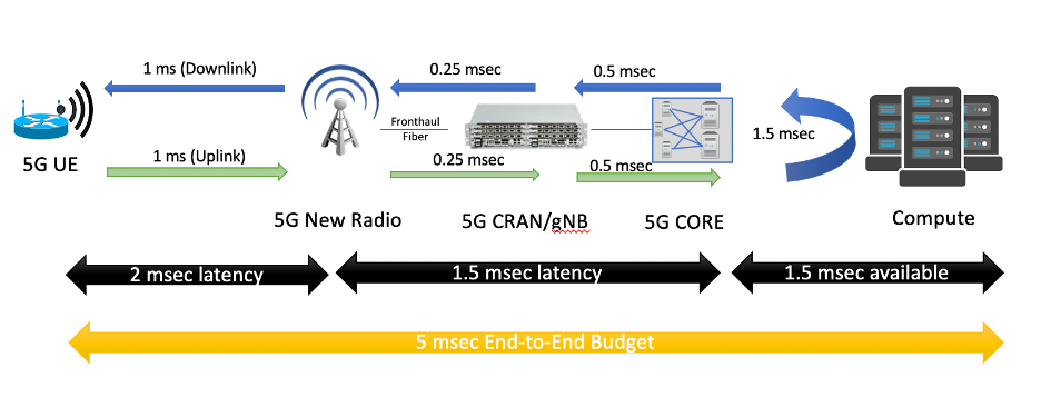
Figure 1. Example latency budget with 5G and Edge Computing.
Public Cloud Service Providers and 3rd-Party Edge Compute (EC) Providers are deploying Edge instances to better serve their end users and applications, A multitude of these applications require close inter-working with the Mobile Edge deployments to provide predictable latency, throughput, reliability and other requirements.
The need to interface and exchange information through open APIs will allow competitive offerings for Consumers, Enterprises and Vertical Industry end-user segments. These APIs are not limited to providing basic connectivity services but will include ability to deliver predictable data rate, predictable latency, reliability, service insertion, security, AI and RAN analytics, network slicing and more.
These capabilities are needed to support a multitude of emerging applications such as AR/VR, Industrial IoT, autonomous vehicles, drones, Industry 4.0 initiatives, Smart Cities, Smart Ports. Other APIs will include exposure to edge orchestration and management, Edge monitoring (KPIs), and more. These open APIs will be foundation for service and instrumentation capabilities when integrating with public cloud development environments.
The purpose of Public Cloud Edge Interface (PCEI) Blueprint family is to specify a set of open APIs for enabling interworking between multiple functional domains that provide Edge capabilities/applications and require close interworking between the Mobile Edge, the Public Cloud Core and Edge as well as the 3rd-Party Edge functions. The high-level relationships between the functional domains is shown in the figure below:
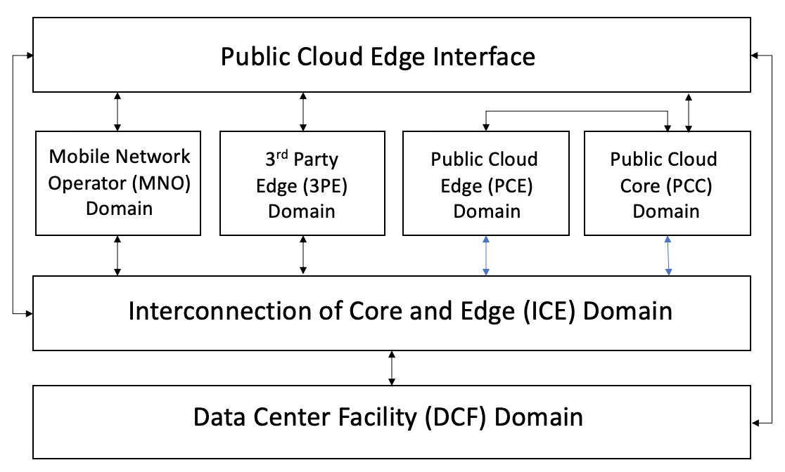
Figure 2. PCEI Functional Domains.
The Data Center Facility (DCF) Domain. The DCF Domain includes Data Center physical facilities that provide the physical location and the power / space infrastructure for other domains and their respective functions.
The Interconnection of Core and Edge (ICE) Domain. The ICE Domain includes the physical and logical interconnection and networking capabilities that provide connectivity between other domains and their respective functions.
The Mobile Network Operator (MNO) Domain. The MNO Domain contains all Access and Core Network Functions necessary for signaling and user plane capabilities to allow for mobile device connectivity.
The Public Cloud Core (PCC) Domain. The PCC Domain includes all IaaS/PaaS functions that are provided by the Public Clouds to their customers.
The Public Cloud Edge (PCE) Domain. The PCE Domain includes the PCC Domain functions that are instantiated in the DCF Domain locations that are positioned closer (in terms of geographical proximity) to the functions of the MNO Domain.
The 3rd party Edge (3PE) Domain. The 3PE domain is in principle similar to the PCE Domain, with a distinction that the 3PE functions may be provided by 3rd parties (with respect to the MNOs and Public Clouds) as instances of Edge Computing resources/applications.
The PCEI Reference Architecture and the Interface Reference Points (IRP) are shown in the figure below. For the full description of the PCEI Reference Architecture please refer to the PCEI Architecture Document.
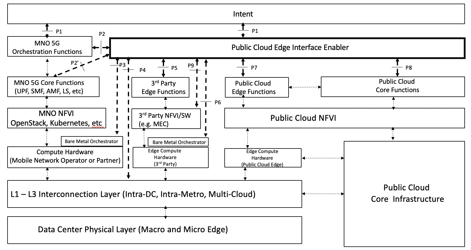
Figure 3. PCEI Reference Architecture.
The PCEI Reference Architecture layers are described below:
The PCEI Data Center (DC) Physical Layer belongs to the DCF Domain and provides the physical DC infrastructure located in appropriate geographies (e.g. Metropolitan Areas). It is assumed that the Public Cloud Core infrastructure is interfaced to the PCEI DC Physical Layer through the PCEI L1-L3 Interconnection layer.
The PCEI L1-L3 Interconnection Layer belongs to the ICE Domain and provides physical and logical interconnection and networking functions to all other components of the PCEI architecture.
Within the MNO Domain, the PCEI Reference Architecture includes the following layers:
Within the Public Cloud Domain, the PCEI Reference Architecture includes the following layers:
Within the 3rd Party Edge Domain, the PCEI Reference Architecture includes the following layers:
The PCEI Enabler. A set of functions that facilitate the interworking between PCEI Architecture Domains. The structure of the PCEI Enabler is described later in this document.
The PCEI Intent Layer. An optional component of the PCEI Architecture responsible for providing the users of PCEI a way to express and communicate their intended functional, performance and service requirements.
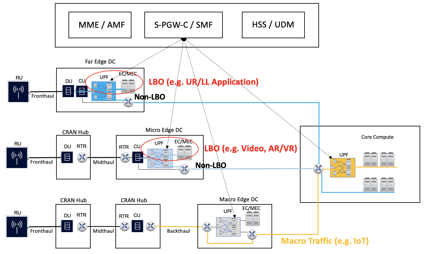
Figure 4. User Plane Function Distribution and Traffic Local Break-Out.
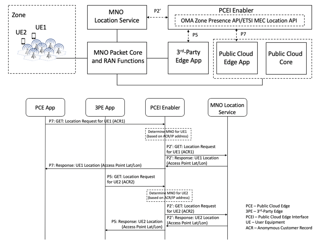
Figure 5. Location Services facilitated by PCEI.