...
Latency can be used as a very good example to illustrate this point. One of the most intriguing possibilities with 5G is the ability to deliver very low end to end latency. A common example is the 5ms round-trip device to application latency target. If we look closely at this latency budget, it is not hard to see that to achieve this goal a new physical aggregation infrastructure is needed. This is because the 5ms budget includes all radio network, transport and processing delays on the path between the application running on User Equipment (UE) and the application running on the compute/server side. Given that at least 2ms will be required for the “air interface”, the remaining 3ms is all that’s left for the transport and the application processing budget. The figure below illustrates the end-to-end latency budget in a 5G network.
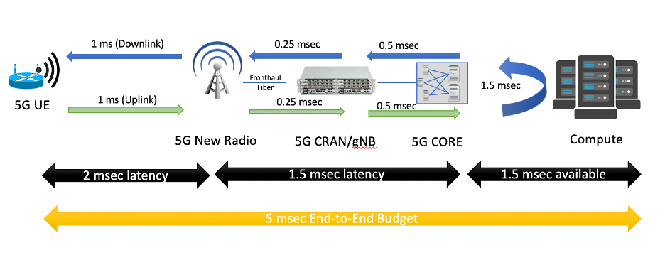
Figure 24. Example latency budget with 5G and Edge Computing.
...
The purpose of Public Cloud Edge Interface (PCEI) Blueprint family is to specify a set of open APIs for enabling interworking between multiple functional domains that provide Edge capabilities/applications and require close interworking between the Mobile Edge, the Public Cloud Core and Edge as well as the 3rd-Party Edge functions. The high-level relationships between the functional domains is shown in the figure below:
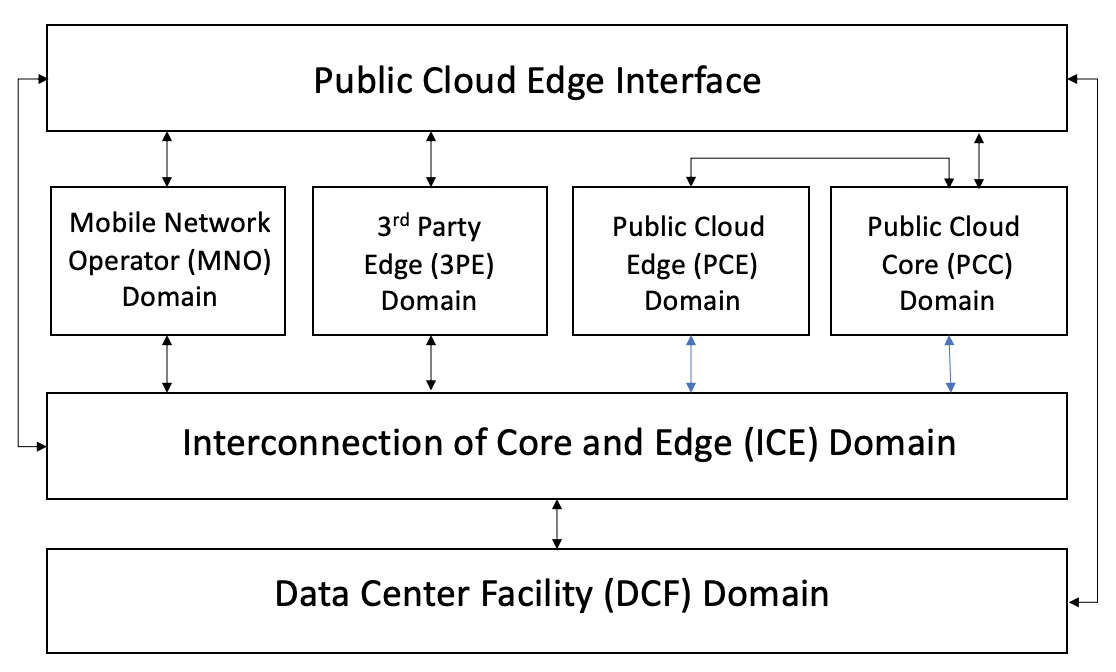
Figure 25. PCEI Functional Domains.
...
The PCEI Reference Architecture and the Interface Reference Points (IRP) are shown in the figure below. For the full description of the PCEI Reference Architecture please refer to the PCEI Architecture Document.
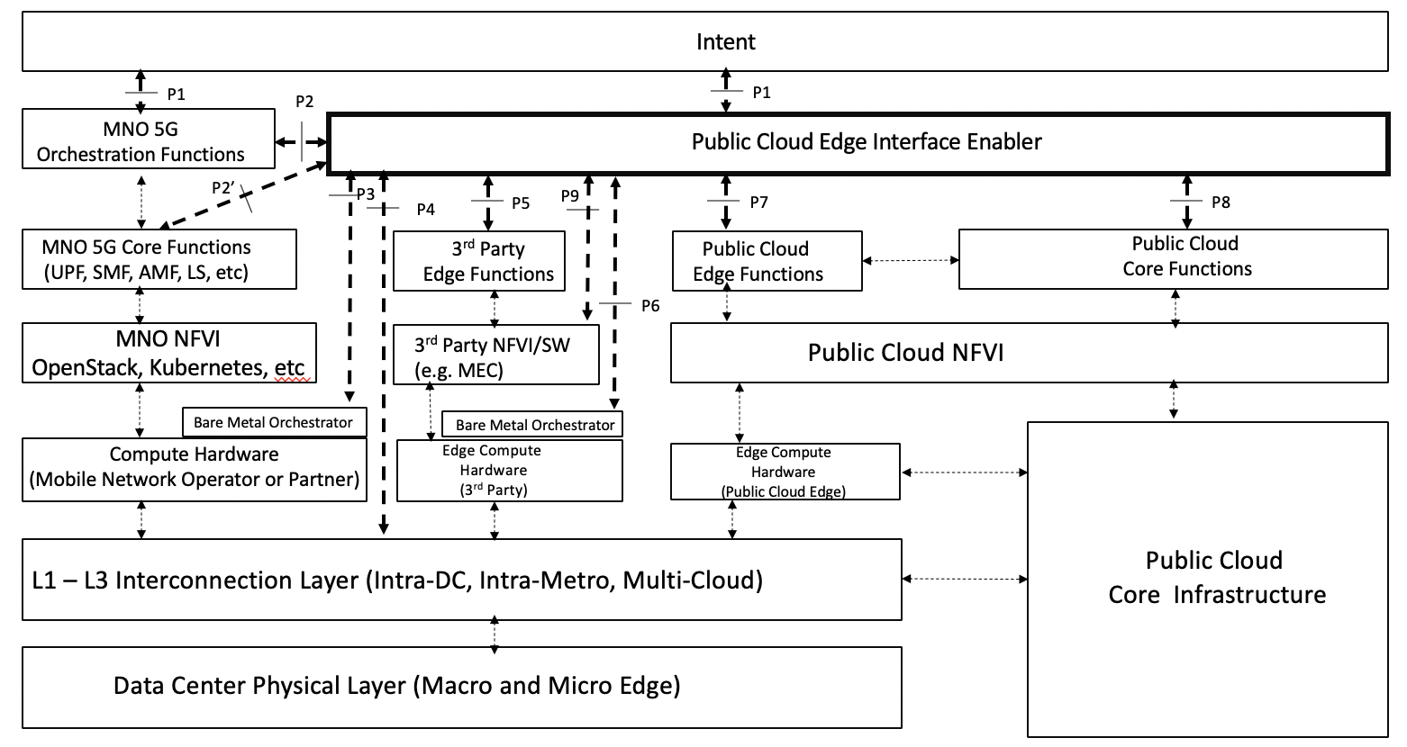
Figure 36. PCEI Reference Architecture.
...
- MNO hosts UPF/SPGW-U in their network.
- MNO provisions all UPF functions.
- MNO may request UPF Interconnection for SGi/N6 interface in a required Metro to 3PE/PCE via APIs (on P2)
- Bare Metal Orchestration Provider and Interconnect Provider expose Data Center Location / Metro to PCEI Enabler via APIs (on P3 and P4)
- 3PE and PCE providers expose Data Center Location / Metro to PCEI Enabler via APIs (on P5 and P8/P7)
- PCEI Enabler may request Bare Metal Orchestration for Distributed UPF via APIs (on P3)
- PCEI Enabler may request Interconnect for MNO UPF (L2/L3) via APIs (on P4)
- PCEI Enabler may request PCC/PCE and/or 3PE Controller to instantiate workload instances for LBO processing via APIs (on P8/P5)
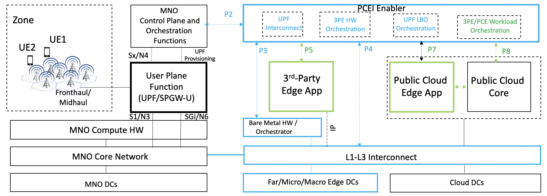
Figure 7. UPF N6/SGi Interconnection to 3PE/PCE/PCC Scenario.
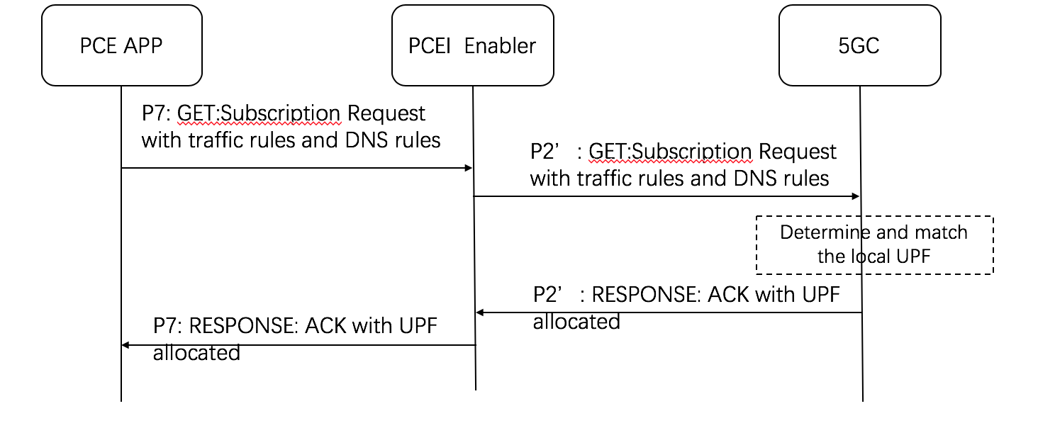
UPF Placement Scenario
Assumptions:
- MNO supports CUPS (5G NSA) and/or UPF (5G SA).
- MNO may request UPF Placement / Metro, and 3PE/PCE Access / Metro, via APIs (on P2)
- Bare Metal Orchestration Provider and Interconnect Provider expose Data Center Location / Metro to PCEI Enabler via APIs (on P3 and P4)
- 3PE and PCE providers expose Data Center Location / Metro to PCEI Enabler via APIs (on P5 and P8/P7)
- PCEI Enabler may request Bare Metal Orchestration for Distributed UPF via APIs (on P3)
- PCEI Enabler may request Bare Metal Orchestration for 3PE via APIs (on P3)
- PCEI Enabler may request Interconnect for Distributed UPF N3/S1 and N6/SGi traffic (L2/L3) via APIs (on P4)
- PCEI Enabler may expose UPF management access to MNO
- MNO may provision the Distributed UPF over management access
- PCEI Enabler may provision UPF connectivity and LBO configuration (based on the UPF provisioning model) over P2’ using appropriate protocols
- PCEI Enabler may request PCC/PCE and/or 3PE Controller to instantiate workload instances for LBO processing via APIs (on P8/P5)
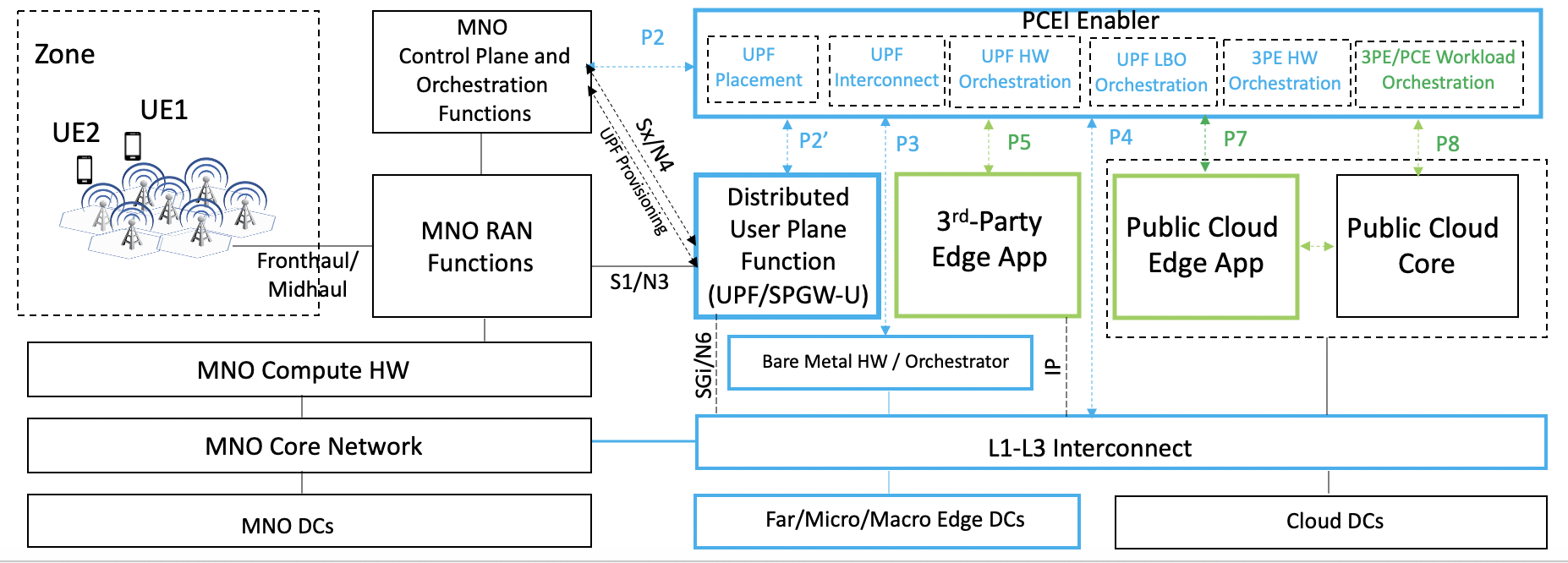
Figure 8. UPF Distribution/Placement and N3/S1 Interconnection to MNO, N6/SGi Interconnection to 3PE/PCE/PCC Scenario.
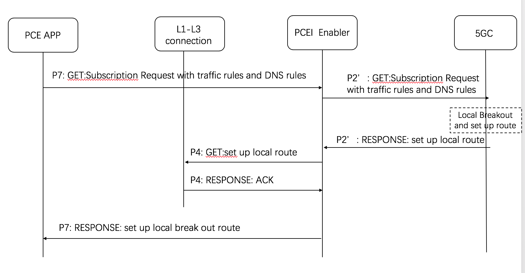
UPF Placement, Interconnection and Local Break-Out Options
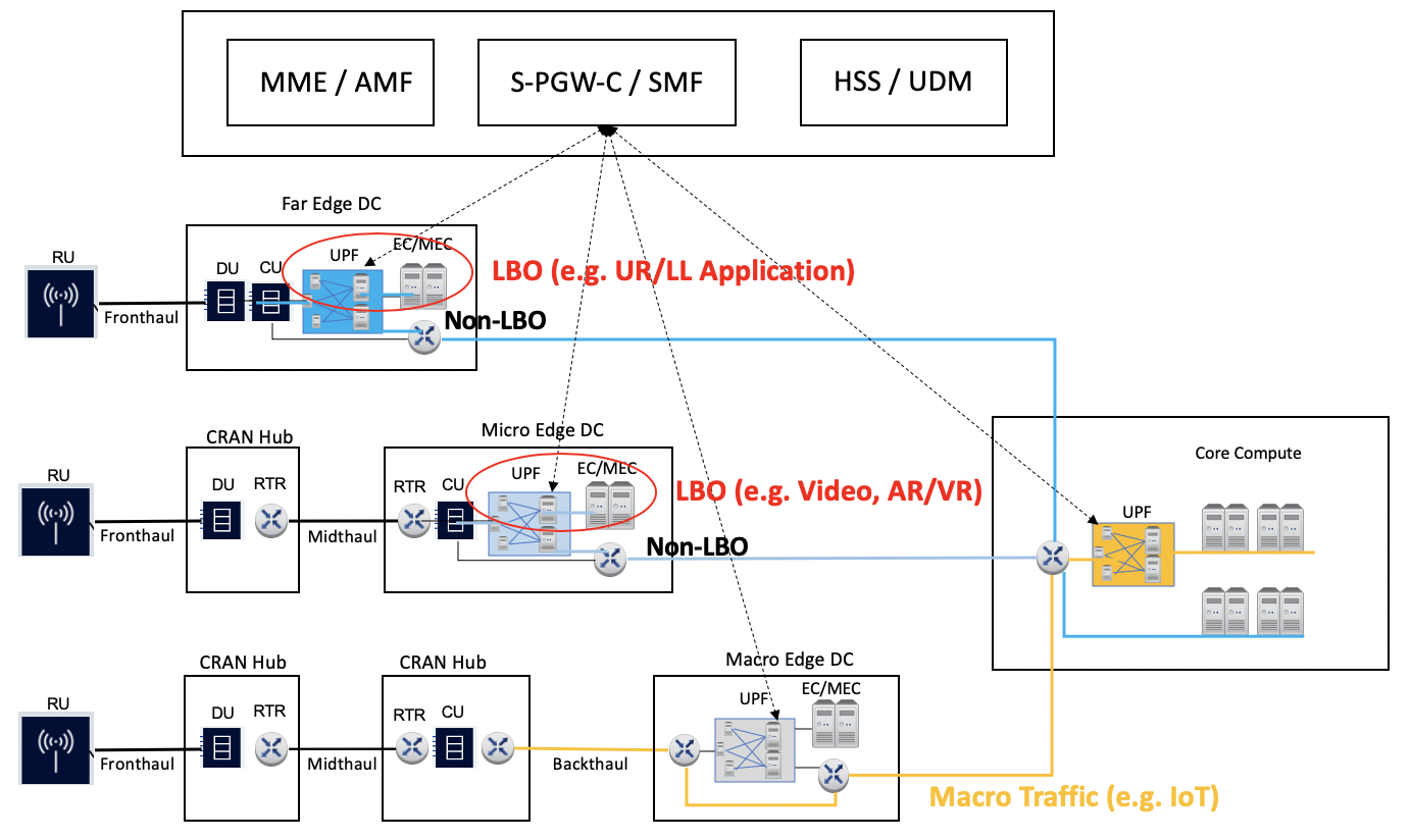
Figure 49. User Plane Function Distribution and Traffic Local Break-Out.
...
UPF Distribution:
Local Breakout:
Location Services
...
(LS)
This use case targets obtaining geographic location of a specific UE provided by the 4G/5G network, identification of UEs within a geographical area as well as facilitation of server-side application workload distribution based on UE and infrastructure resource location.
Assumptions:
- MNO provides a Location Service (LS) compliant with OMA Zonal Presence API (OMA-TS-REST_NetAPI_ZonalPresence)
- MNO may expose the Location Service via the Network Exposure Function (NEF)
- A Public Cloud Edge (PCE) instance is associated with a Zone (collection of Access Points such as small cells) provided by an MNO
- A 3rd-Party Edge (3PE) instance is associated with a Zone (collection of Access Points such as small cells) provided by an MNO
- An application/workload in the PCE requires Location Information (e.g. coordinates of the Access Point) for the UE/subscriber
- An application/workload in the 3PE requires Location Information (e.g. coordinates of the Access Point) for the UE/subscriber
- PCEI Enabler facilitates Zonal Presence API Request/Response routing between PCE and the MNO LS and between the 3PE and the MNO LS

Figure 12. Location Services facilitated by PCEI.
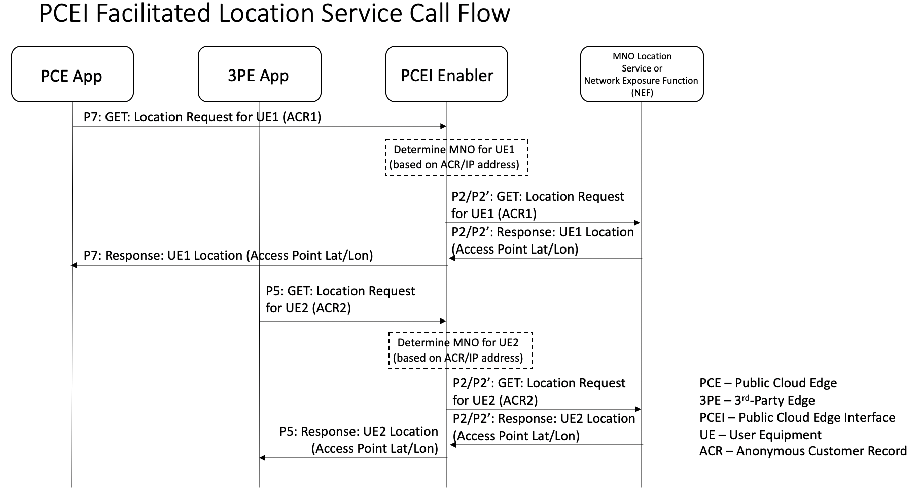
Figure 13
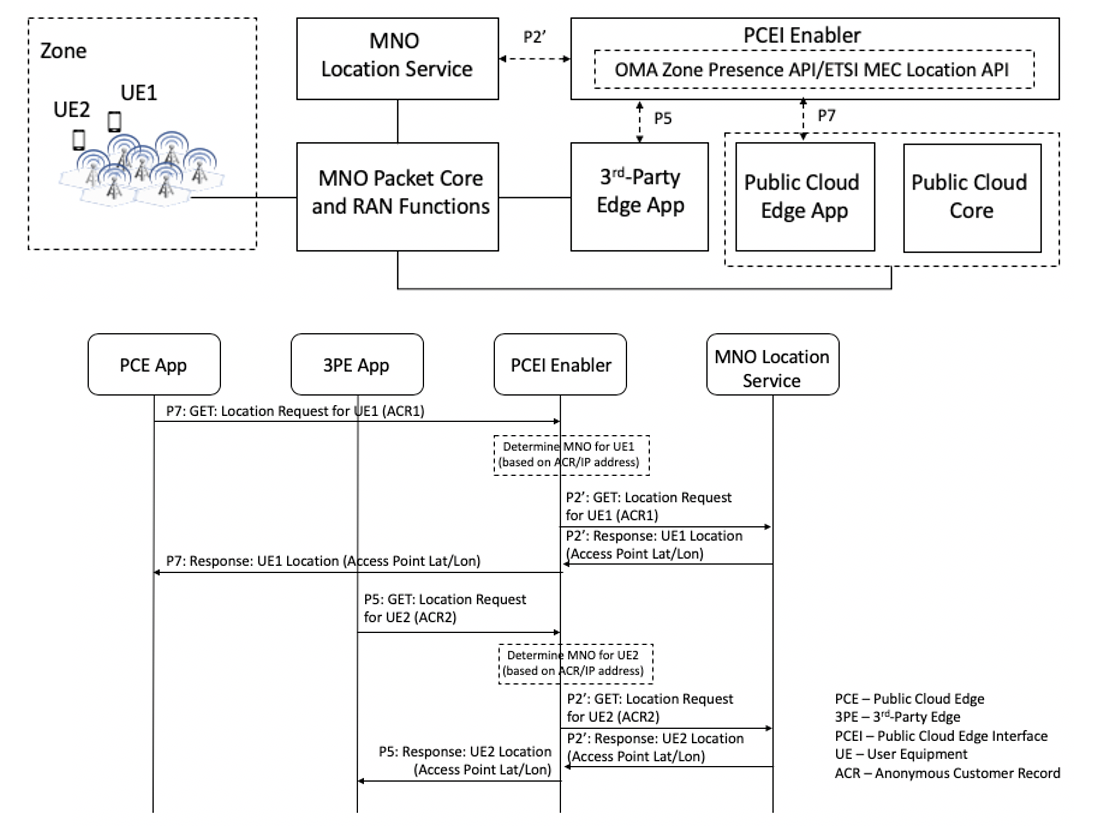
Figure 5. Location Services facilitated by PCEI.
Acknowledgements
Please add your names here
...