| Table of Contents |
|---|
Live demo
Cloud server management platform: https://dev.socnoc.cn/
Send email to demo@socnoc.ai for test account.
Blueprint overview/Introduction
Integrated Edge Cloud(IEC) is an Akraino approved blueprint family and part of Akraino Edge Stack, which intends to develop a fully integrated edge infrastructure solution, and the project is completely focused on Edge Computing. This open-source software stack provides critical infrastructure to enable high performance, reduce latency, improve availability, lower operational overhead, provide scalability, address security needs, and improve fault management. The IEC project will address multiple edge use cases and industry, not just the Telco Industry. IEC intends to develop solution and support of carrier, provider, and the IoT networks.
IEC Type 5 Release 6 is an innovative architecture for small-size edge cloud using data processor.
To meet the demanding increase of 5G data and the utilize the advantage of low latency and high bandwidth of 5G technologies, the number of small-size datacenter is increasing dramatically. Research shows there shall be more than 2.8 million cloudlet datacenters with less than 200 servers connected near the 5G tower. In IEC Type 5 project, we will build an innovative architecture for small-size edge cloud computing using latest and greatest data processor.
Application Case
- New networking architecture to lower the TCO of edge infrastructure
- TCP/IP compatible and cloud native for develops and developers
- Green to protect the environment for lasting development
- Scalable and composable to meet the dynamical workload
Where on the Edge
Business Drivers: SmartNIC is located in edge cloud servers, which belongs to the EC infrastructure and VPC, 5G UPF can use SmartNIC to accelerate the performance.
System Architecture
1. Extending PCIe Transport
To achieve low cost and low power, in R6, we introduce the latest and greatest technology to connect two servers directly with PCIe links via innovative data processors. In this scenario, we eliminate the legacy network adapters (such as NIC, optics and legacy network switches). In typical application, with PCIe networking, we can reduce the number of connection components by 75%.
2. PCIe Networking and Cloud-on-Board
By the advantage of PCIe networking, we can unified the system-on-board (SoB) connection and the cloud cluster topologies into one single and simple architecture, which we named as Cloud-on-Board (CoB) Architecture.
In the CoB architecture, we can connect CPU directly without additional adapters.
2.1 PCIe Extending DPU Cluster:
IEC Type 5 System Architecture
2.2 Roadmap
In R6, we introduce PCIe based data fabric. In the future, we will include CXL or UCIe based as well.
3. Hardware Design
1. System Architecture
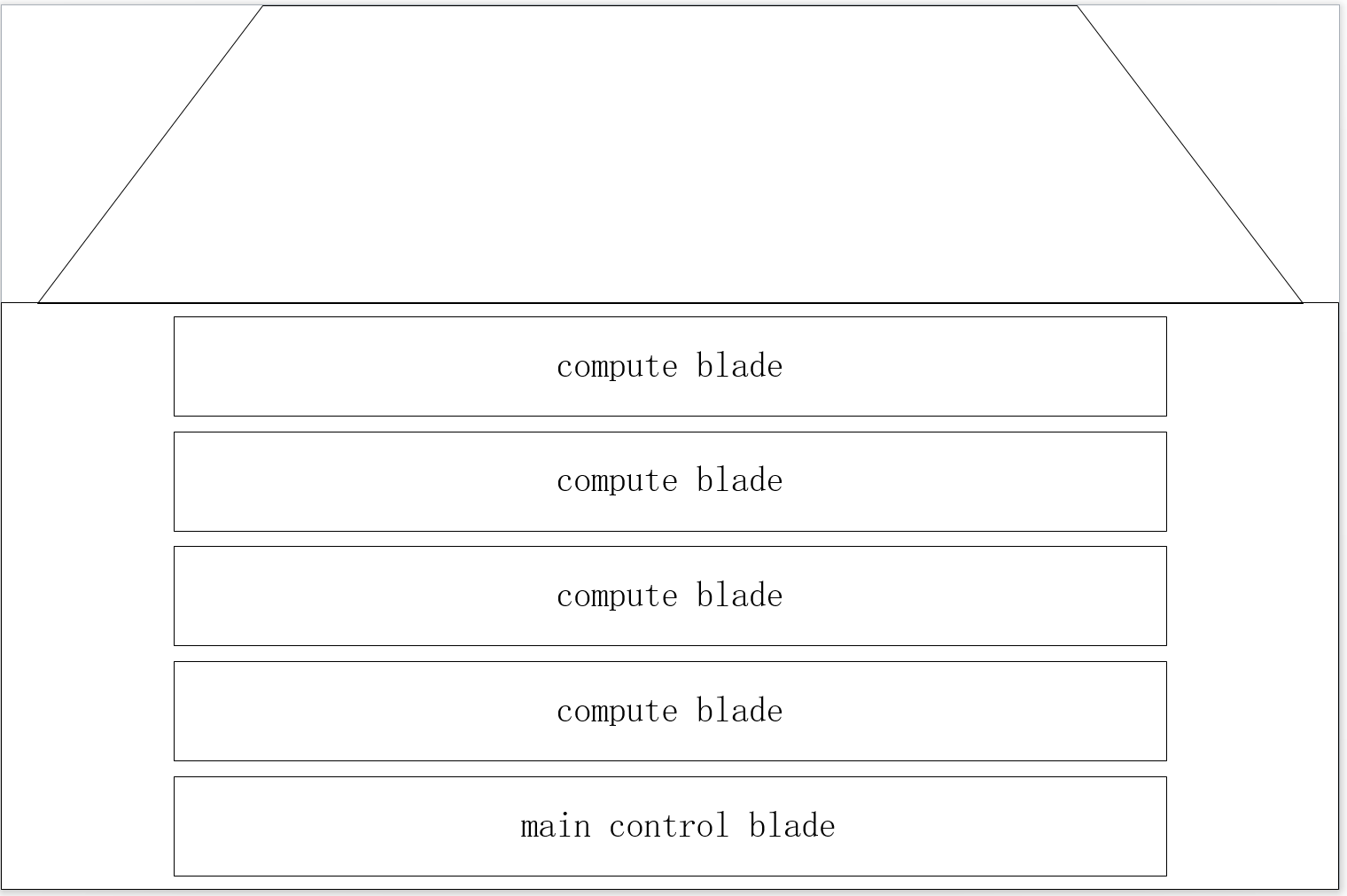
The prototype consists of the main control blade, compute blade, switching backplane, heat dissipation system, power supply, and chassis.
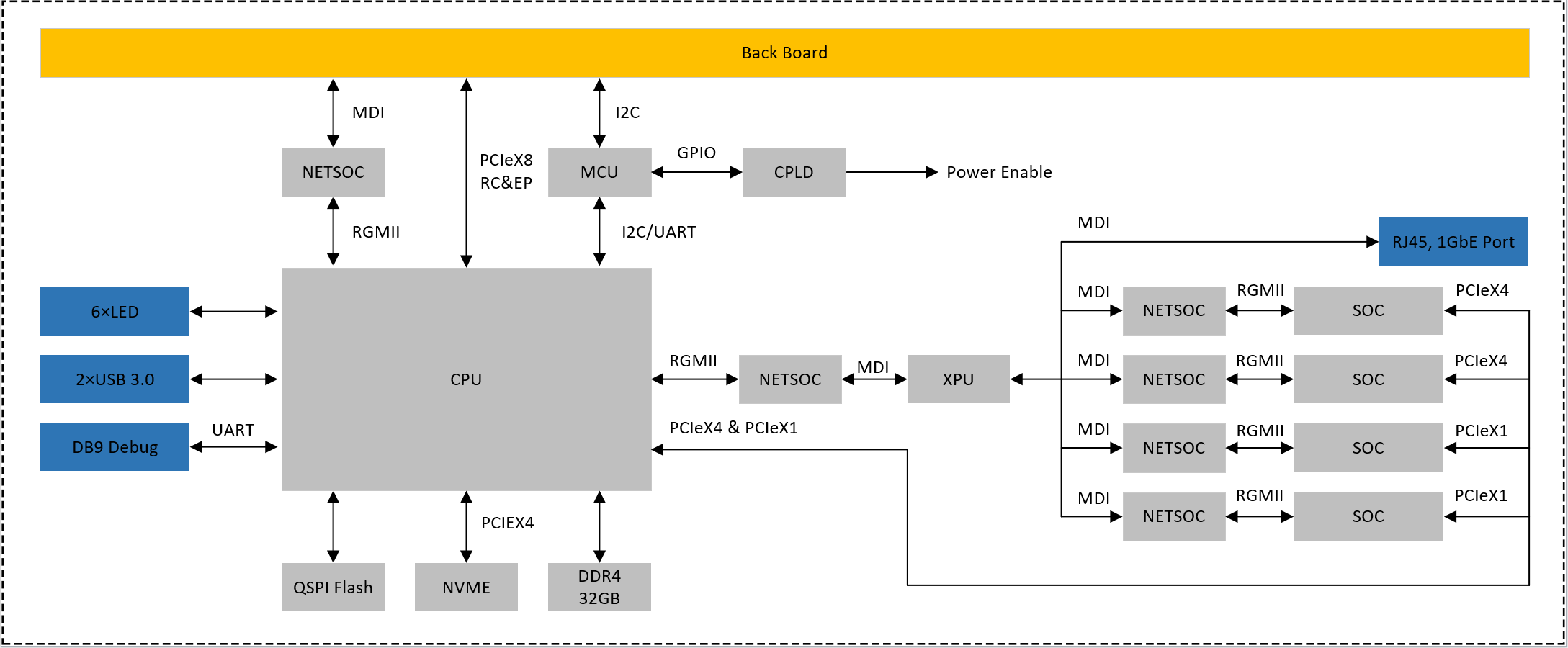
1.1 main control blade
CPU choose DDR4 particles as a memory / 8, 32 gb capacity, 3200 MTPS physical rate;
SOC choose DDR4 particles as memory, 8 gb capacity, 3200 MTPS physical rate;
CPU between 8 and SOC use PCle Gen3X16 connection;
CPU by PCle Gen3X4 mount NVME hard disk, hard disk capacity of not less than 256 gb;
NETSOC via PCIE connection, providing two 10 g front-end ports;
Provide panel with DP, HDMI, USB3.1, Audio interface;Provide the necessary condition to the panel lights;
Reserved debug serial port debugging so;
1.2 compute blade
To provide back PCle Gen 3 by 8 signal, can be configured to RC and EP;
To provide back 1 gbe MDI network signal;
To provide back IPMI management based on 12 c interface;To provide panel 1 gbe network, USES the RJ45 interface;
To provide panel debug serial port, using the DB9 interface;
Provide panel with two USB 3.0 interface, using the Type - A interface;Provide panel with six software programmable control indicator light;
CPU by PCle Gen3X4 mount NVME hard disk, hard disk capacity of not less than 256 gb;
Using DDR4 as a memory, not less than 32 gb capacity, interface physical rate not less than 3200 MTPS;
Through the network exchange chip 4 soc and XPU connection module, access rate to 1 GBPS;
Each SOC module USES LPDDR4X memory, not less than 8 gb capacity, rate of not less than 4266 MTPS;
CPU through two PCle Gen3X4 and 2 PCle Gen3X1 four SOC and connectivity;
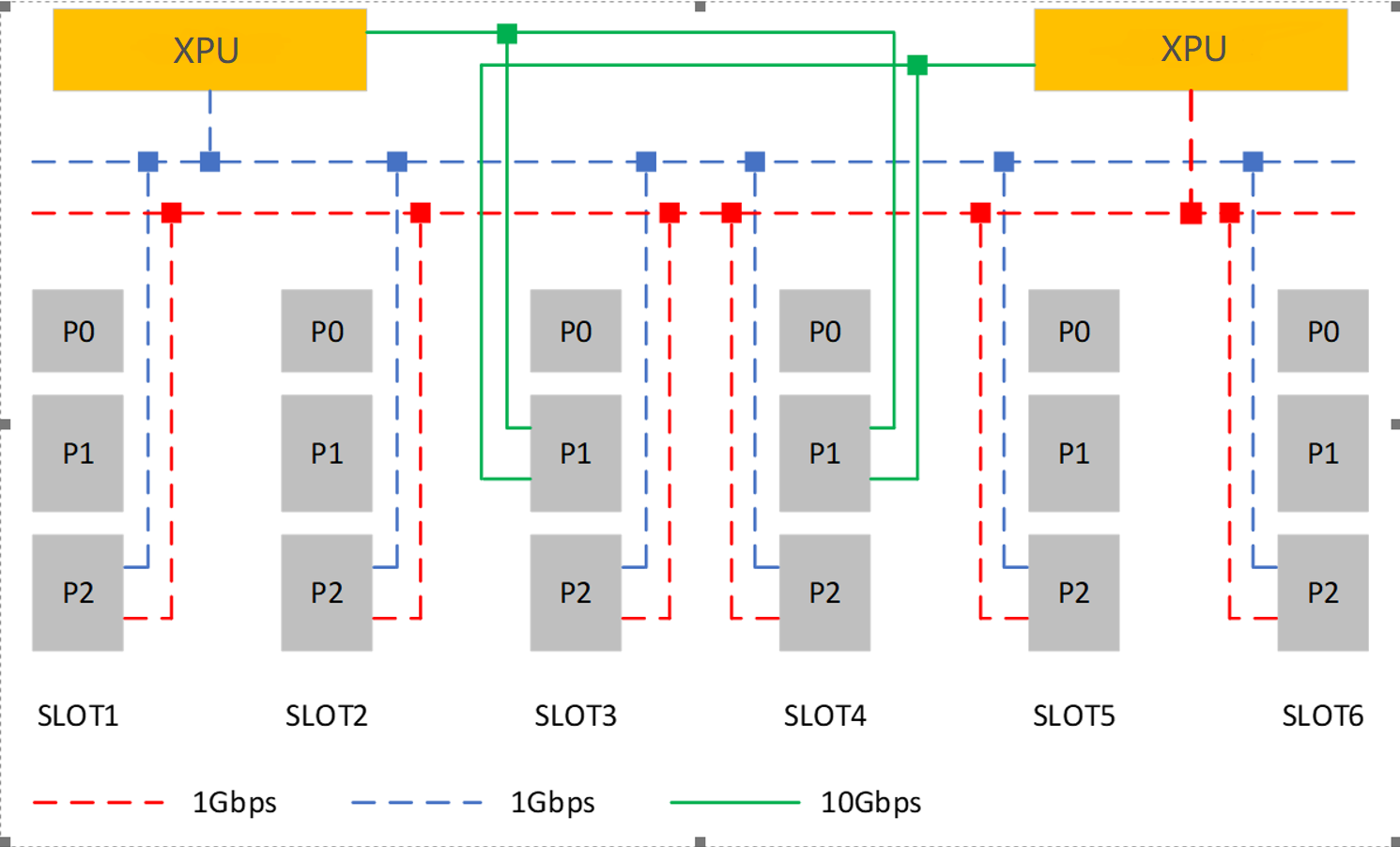
1.3 switching backplaner
Using XPU in exchange for chips, two pieces of XPU are redundant;
Each XPU can provide up to eight 1 gbe port, each slot P2 side provide 2 road 1 gbe interface to be redundant XPU;
Each XPU can provide up to two 10 gbe port, the P1 end of the slot number 3 and 4 provide 2 road 10 gbe interface to the XPU are redundantBack to the slot provides IPMI management interface based on 12 c, located in each slot P0 end;
Back to the slot provides auxiliary power AUX + 5 v and + 12 v power supply, is located in each slot P0 end;
The backplane provides the engine fan power supply and control.
2. Hardware Design
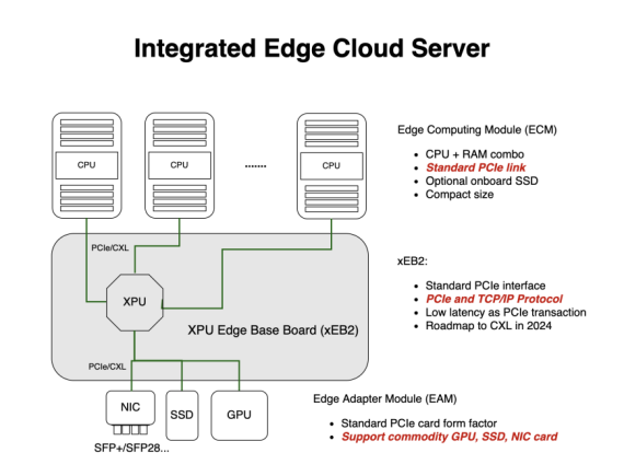
3.3.1 Cloud-on-Board (CoB) Architecture
...
3) Edge Adapter Module (EAM): PCIe-compatible Device, such as GPU, NIC, SSD etc.
3.2 Networking Topology
In CoB design, we have multiple networks. At least one PCIe networking for multiple CPUs. Also we can introduce more connections as well as traditional RJ45 as the management ports as well. Hence all CoB Hardware are cloud native compatible at the beginning.
Networking in CoB system for Cloud Native Applications
Cloud Native Server Reference Design
At least, we pack all components together, and give a reference design as below.
Licensing
GNU/common license
...


