1. System Architecture
The prototype consists of the main control blade, compute blade, switching backplane, heat dissipation system, power supply, and chassis.
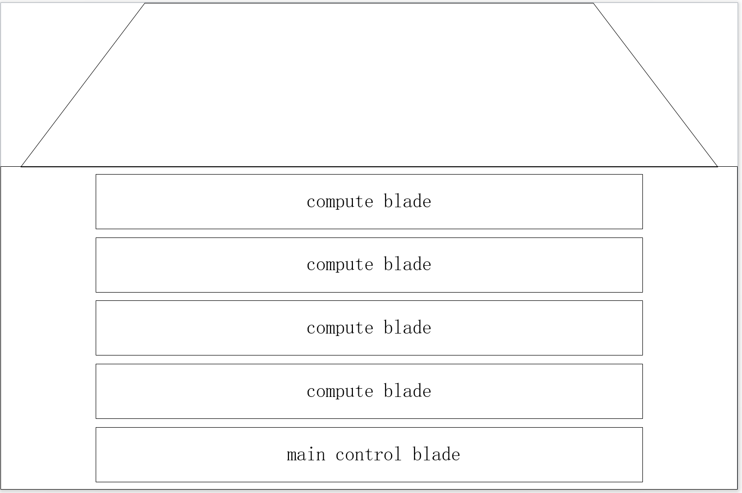
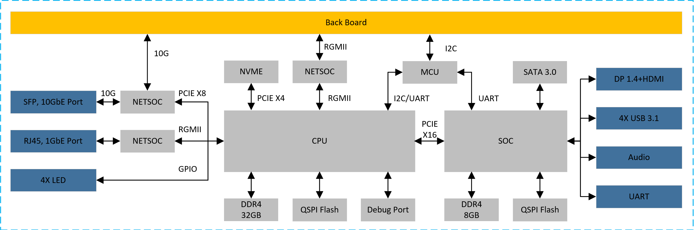
1.1 main control blade
CPU choose DDR4 particles as a memory / 8, 32 gb capacity, 3200 MTPS physical rate;
SOC choose DDR4 particles as memory, 8 gb capacity, 3200 MTPS physical rate;
CPU between 8 and SOC use PCle Gen3X16 connection;
CPU by PCle Gen3X4 mount NVME hard disk, hard disk capacity of not less than 256 gb;
NETSOC via PCIE connection, providing two 10 g front-end ports;
Provide panel with DP, HDMI, USB3.1, Audio interface;Provide the necessary condition to the panel lights;
Reserved debug serial port debugging so;
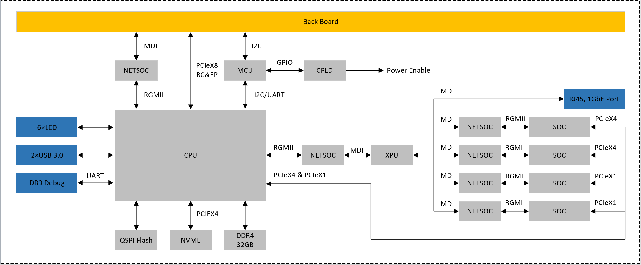
1.2 compute blade
To provide back PCle Gen 3 by 8 signal, can be configured to RC and EP;
To provide back 1 gbe MDI network signal;
To provide back IPMI management based on 12 c interface;To provide panel 1 gbe network, USES the RJ45 interface;
To provide panel debug serial port, using the DB9 interface;
Provide panel with two USB 3.0 interface, using the Type - A interface;Provide panel with six software programmable control indicator light;
CPU by PCle Gen3X4 mount NVME hard disk, hard disk capacity of not less than 256 gb;
Using DDR4 as a memory, not less than 32 gb capacity, interface physical rate not less than 3200 MTPS;
Through the network exchange chip 4 soc and XPU connection module, access rate to 1 GBPS;
Each SOC module USES LPDDR4X memory, not less than 8 gb capacity, rate of not less than 4266 MTPS;
CPU through two PCle Gen3X4 and 2 PCle Gen3X1 four SOC and connectivity;
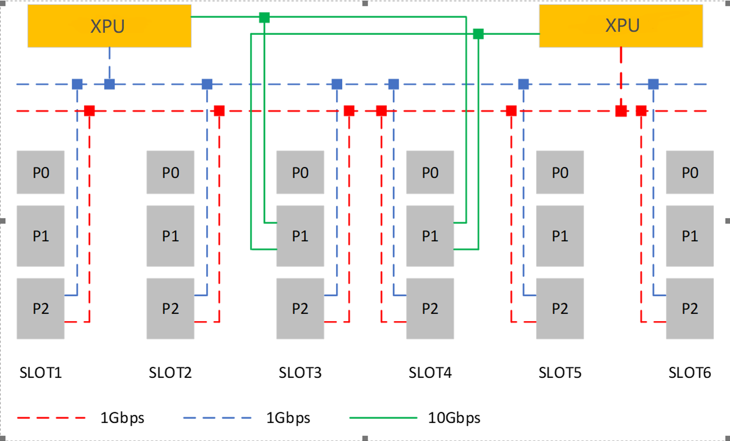
1.3 switching backplaner
Using XPU in exchange for chips, two pieces of XPU are redundant;
Each XPU can provide up to eight 1 gbe port, each slot P2 side provide 2 road 1 gbe interface to be redundant XPU;
Each XPU can provide up to two 10 gbe port, the P1 end of the slot number 3 and 4 provide 2 road 10 gbe interface to the XPU are redundantBack to the slot provides IPMI management interface based on 12 c, located in each slot P0 end;
Back to the slot provides auxiliary power AUX + 5 v and + 12 v power supply, is located in each slot P0 end;
The backplane provides the engine fan power supply and control.
2. Hardware Design
3.1 Cloud-on-Board (CoB) Architecture
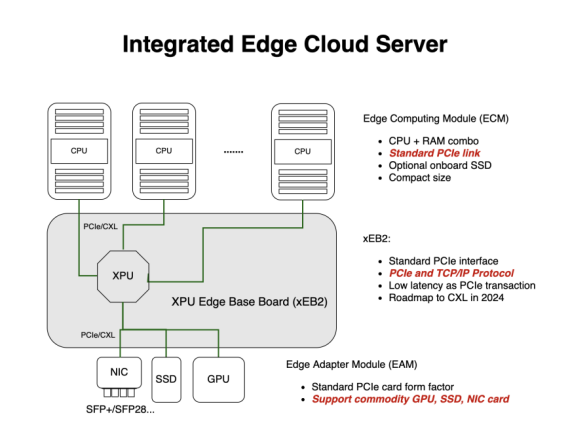
For general computing, we introduce the CoB with three major components:
1) Edge Computing Module (ECM): CPU+RAM+OS SSD combo,
2) Edge Base Board (EB2): for PCIe Data Fabric,
3) Edge Adapter Module (EAM): PCIe-compatible Device, such as GPU, NIC, SSD etc.
Licensing
GNU/common license