...
The prototype consists of the main control blade, compute blade, switching backplane, heat dissipation system, power supply, and chassis.
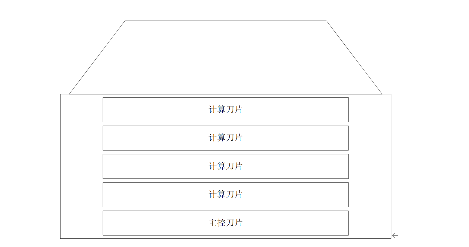
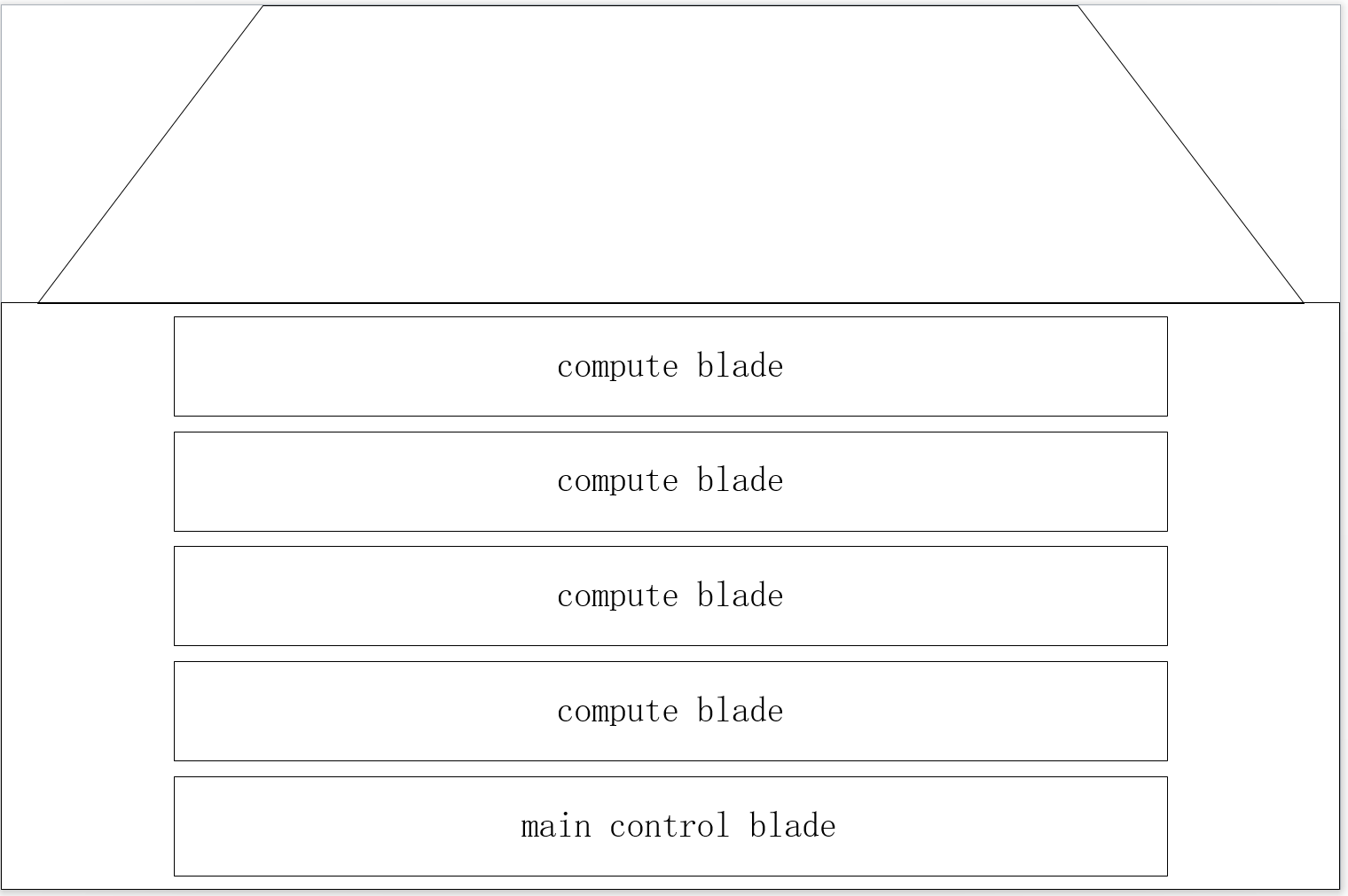
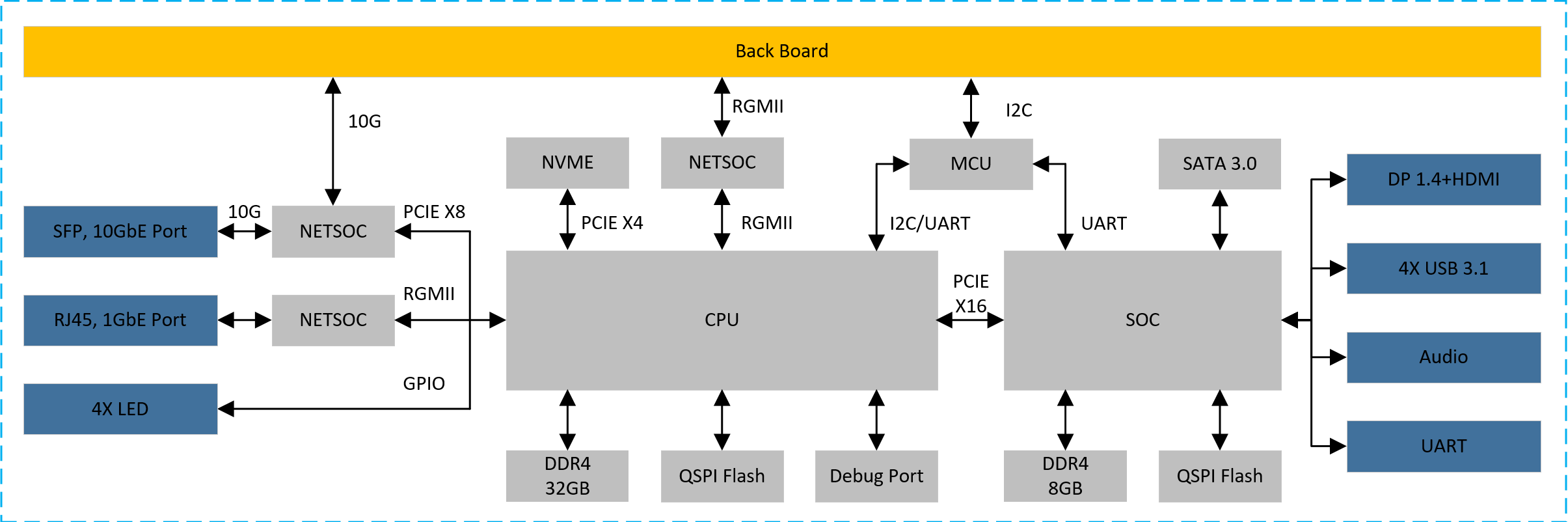
1.1 main control blade
By the advantage of PCIe networking, we can unified the system-on-board (SoB) connection and the cloud cluster topologies into one single and simple architecture, which we named as Cloud-on-Board (CoB) Architecture.

In the CoB architecture, we can connect CPU directly without additional adapters.
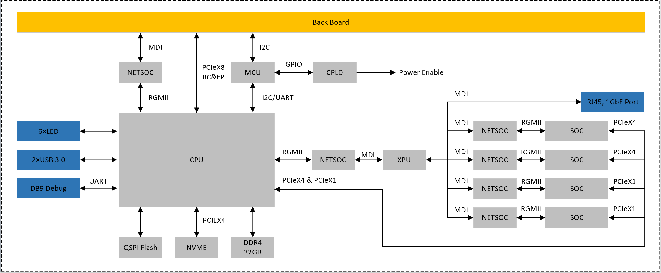
1.2 compute blade

1.3 switching backplaner
CPU choose DDR4 particles as a memory / 8, 32 gb capacity, 3200 MTPS physical rate;
SOC choose DDR4 particles as memory, 8 gb capacity, 3200 MTPS physical rate;
CPU between 8 and SOC use PCle Gen3X16 connection;
CPU by PCle Gen3X4 mount NVME hard disk, hard disk capacity of not less than 256 gb;
NETSOC via PCIE connection, providing two 10 g front-end ports;
Provide panel with DP, HDMI, USB3.1, Audio interface;Provide the necessary condition to the panel lights;
Reserved debug serial port debugging so;
1.2 compute blade
To provide back PCle Gen 3 by 8 signal, can be configured to RC and EP;
To provide back 1 gbe MDI network signal;
To provide back IPMI management based on 12 c interface;To provide panel 1 gbe network, USES the RJ45 interface;
To provide panel debug serial port, using the DB9 interface;
Provide panel with two USB 3.0 interface, using the Type - A interface;Provide panel with six software programmable control indicator light;
CPU by PCle Gen3X4 mount NVME hard disk, hard disk capacity of not less than 256 gb;
Using DDR4 as a memory, not less than 32 gb capacity, interface physical rate not less than 3200 MTPS;
Through the network exchange chip 4 soc and XPU connection module, access rate to 1 GBPS;
Each SOC module USES LPDDR4X memory, not less than 8 gb capacity, rate of not less than 4266 MTPS;
CPU through two PCle Gen3X4 and 2 PCle Gen3X1 four SOC and connectivity;
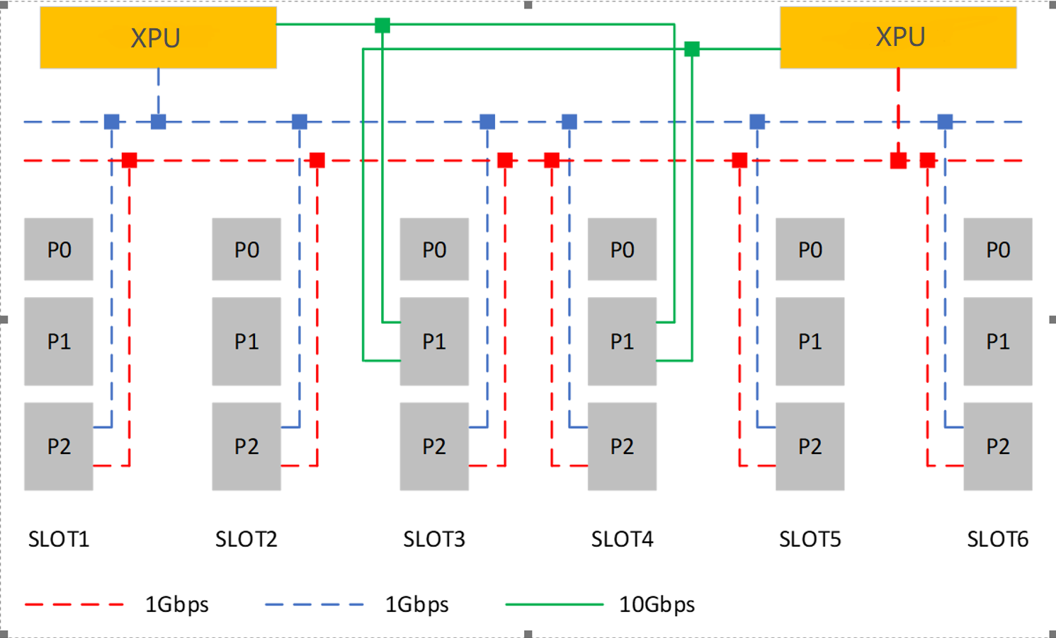
1.3 switching backplaner
Using XPU in exchange for chips, two pieces of XPU are redundant;
Each XPU can provide up to eight 1 gbe port, each slot P2 side provide 2 road 1 gbe interface to be redundant XPU;
Each XPU can provide up to two 10 gbe port, the P1 end of the slot number 3 and 4 provide 2 road 10 gbe interface to the XPU are redundantBack to the slot provides IPMI management interface based on 12 c, located in each slot P0 end;
Back to the slot provides auxiliary power AUX + 5 v and + 12 v power supply, is located in each slot P0 end;
The backplane provides the engine fan power supply and control.

2. Hardware Design
...