Introduction
Why 5G
The 5th Generation of Mobile Networks (a.k.a. 5G) represents a dramatic technological inflection point where the cellular wireless network becomes capable of delivering significant improvements in capacity and performance, compared to the previous generations and specifically the most recent one – 4G LTE.
5G will provide significantly higher throughput than existing 4G networks. Currently 4G LTE is limited to around 150 Mbps. LTE Advanced increases the data rate to 300 Mbps and LTE Advanced Pro to 600Mbps-1 Gbps. The 5G downlink speeds can be up to 20 Gbps. 5G can use multiple spectrum options, including low band (sub 1 GHz), mid-band (1-6 GHz) and mmWave (28, 39 GHz). The mmWave spectrum has the largest available contiguous bandwidth capacity (~1000 MHz) and promises dramatic increases in user data rates. 5G enables advanced air interface formats and transmission scheduling procedures that decrease access latency in the Radio Access Network by a factor of 10 compared to 4G LTE.
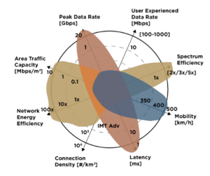
Figure 1. 5G key performance goals.
5G New Radio (5GNR) improves the air interface capacity and the Radio Access Network (RAN) density by utilizing small cells, RAN functional split (separation between the RAN functions such as the Radio Unit, Distributed Unit and Centralized Unit, connected via Fronthaul or Midhaul depending on the split option), Massive Multiple Input Multiple Output (mMIMO) antenna arrays and Beamforming/Beamsteering (for advanced spatial multiplexing), as well as high capacity spectrum options.
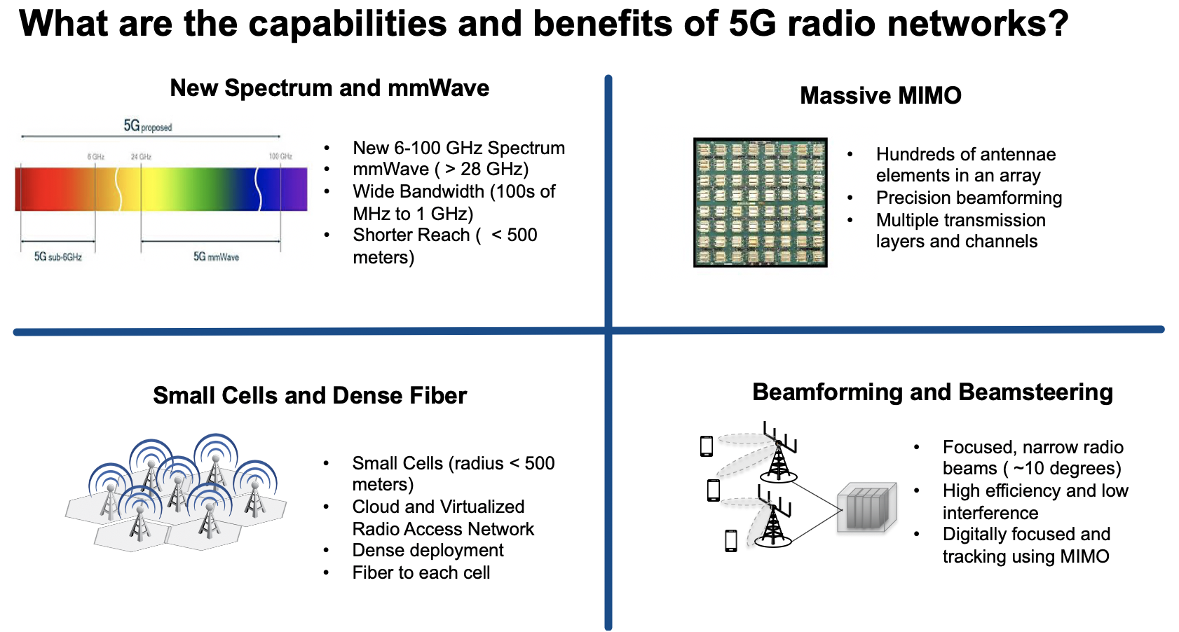
Figure 2. 5G New Radio characteristics.
Among advanced properties of the 5G architecture, Network Slicing represents an attractive capability to enable the use of 5G network and services for a wide variety of use cases on the same infrastructure. Network Slicing (NS) refers to the ability to provision and connect functions within a common physical network to provide resources necessary for delivering service functionality under specific performance (e.g. latency, throughput, capacity, reliability) and functional (e.g. security, applications/services) constraints.
It is important to point out that the keyword “network” refers to the complete system that provides services and not specifically to the transport and networking functions that are part of this system. In the mobile context, the examples of networks are the Evolved Packet System (EPS) delivering 4G services and the 5G System (5GS) delivering 5G services. Both systems include the RAN (LTE, 5GNR), Packet Core (EPC, 5GC) and transport/networking functions that can be used to construct network slices.
The Slicing Must Go On
Network Slicing is particularly relevant to the subject matter of the Public Cloud Edge Interface (PCEI) Blueprint. As shown in the figure below, there is a reasonable expectation that applications enabled by the 5G performance characteristics will need access to diverse resources. This includes conventional traffic flows, such as access from mobile devices to the core clouds (public and/or private) as well as the general access to the Internet, edge traffic flows, such as low latency/high speed access to edge compute workloads placed in close physical proximity to the User Plane Functions (UPF), as well as the hybrid traffic flows that require a combination of the above for distributed applications (e.g. online gaming, AI at the edge, etc). One point that is very important is that the network slices provisioned in the mobile network must extend beyond the N6/SGi interface of the UPF all the way to the workloads running on the edge compute hardware and on the Public/Private Cloud infrastructure. In other words "The Slicing Must Go On" in order to ensure continuity of intended performance for the applications.
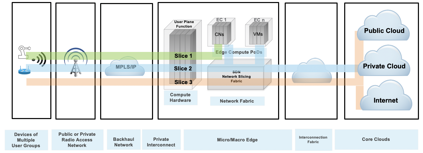
Figure 3. Example of Network Slicing configuration.
The Mobile Edge
The technological capabilities defined by the standards organizations (e.g. 3GPP, IETF) are the necessary conditions for the development of 5G. However, the standards and protocols are not sufficient on their own. The realization of the promises of 5G depends directly on the availability of the supporting physical infrastructure as well as the ability to instantiate services in the right places within the infrastructure.
Latency can be used as a very good example to illustrate this point. One of the most intriguing possibilities with 5G is the ability to deliver very low end to end latency. A common example is the 5ms round-trip device to application latency target. If we look closely at this latency budget, it is not hard to see that to achieve this goal a new physical aggregation infrastructure is needed. This is because the 5ms budget includes all radio network, transport and processing delays on the path between the application running on User Equipment (UE) and the application running on the compute/server side. Given that at least 2ms will be required for the “air interface”, the remaining 3ms is all that’s left for the transport and the application processing budget. The figure below illustrates the end-to-end latency budget in a 5G network.
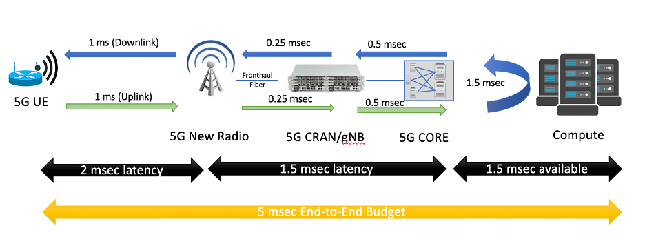
Figure 4. Example latency budget with 5G and Edge Computing.
The Edge-in and Cloud-out Effect
Public Cloud Service Providers and 3rd-Party Edge Compute (EC) Providers are deploying Edge instances to better serve their end users and applications, A multitude of these applications require close inter-working with the Mobile Edge deployments to provide predictable latency, throughput, reliability and other requirements.
The need to interface and exchange information through open APIs will allow competitive offerings for Consumers, Enterprises and Vertical Industry end-user segments. These APIs are not limited to providing basic connectivity services but will include ability to deliver predictable data rate, predictable latency, reliability, service insertion, security, AI and RAN analytics, network slicing and more.
These capabilities are needed to support a multitude of emerging applications such as AR/VR, Industrial IoT, autonomous vehicles, drones, Industry 4.0 initiatives, Smart Cities, Smart Ports. Other APIs will include exposure to edge orchestration and management, Edge monitoring (KPIs), and more. These open APIs will be foundation for service and instrumentation capabilities when integrating with public cloud development environments.
Public Cloud Edge Interface (PCEI)
Overview
The purpose of Public Cloud Edge Interface (PCEI) Blueprint family is to specify a set of open APIs for enabling Multi-Domain Inter-working across functional domains that provide Edge capabilities/applications and require close cooperation between the Mobile Edge, the Public Cloud Core and Edge, the 3rd-Party Edge functions as well as the underlying infrastructure such as Data Centers and Networks. The high-level relationships between the functional domains is shown in the figure below:
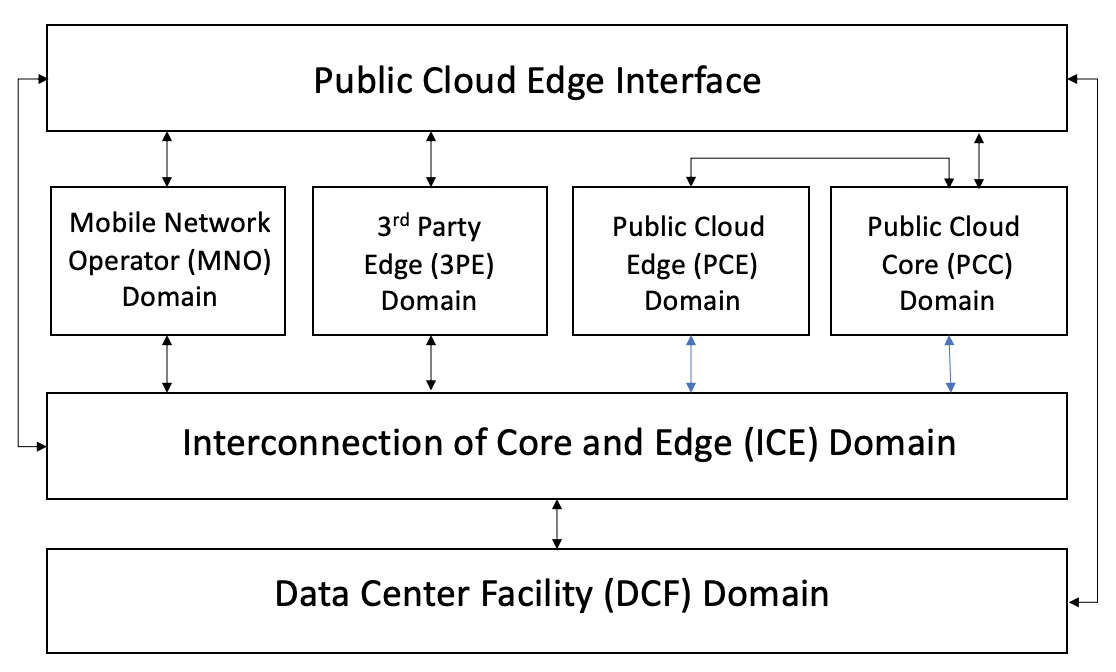
Figure 5. PCEI Functional Domains.
The Data Center Facility (DCF) Domain. The DCF Domain includes Data Center physical facilities that provide the physical location and the power / space infrastructure for other domains and their respective functions.
The Interconnection of Core and Edge (ICE) Domain. The ICE Domain includes the physical and logical interconnection and networking capabilities that provide connectivity between other domains and their respective functions.
The Mobile Network Operator (MNO) Domain. The MNO Domain contains all Access and Core Network Functions necessary for signaling and user plane capabilities to allow for mobile device connectivity.
The Public Cloud Core (PCC) Domain. The PCC Domain includes all IaaS/PaaS functions that are provided by the Public Clouds to their customers.
The Public Cloud Edge (PCE) Domain. The PCE Domain includes the PCC Domain functions that are instantiated in the DCF Domain locations that are positioned closer (in terms of geographical proximity) to the functions of the MNO Domain.
The 3rd party Edge (3PE) Domain. The 3PE domain is in principle similar to the PCE Domain, with a distinction that the 3PE functions may be provided by 3rd parties (with respect to the MNOs and Public Clouds) as instances of Edge Computing resources/applications.
Architecture
The PCEI Reference Architecture and the Interface Reference Points (IRP) are shown in the figure below. For the full description of the PCEI Reference Architecture please refer to the PCEI Architecture Document.
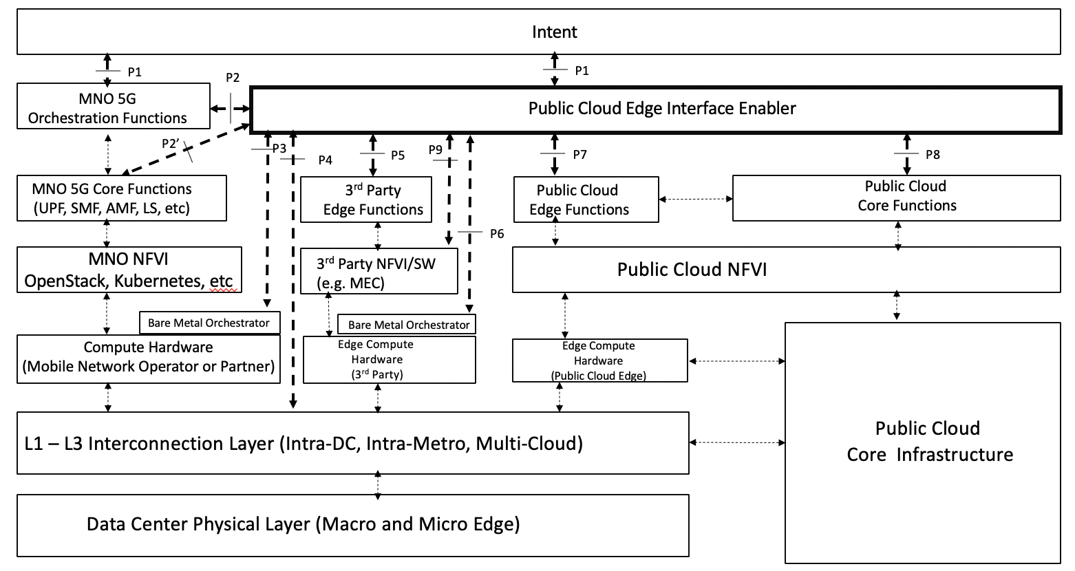
Figure 6. PCEI Reference Architecture.
The PCEI Reference Architecture layers are described below:
The PCEI Data Center (DC) Physical Layer belongs to the DCF Domain and provides the physical DC infrastructure located in appropriate geographies (e.g. Metropolitan Areas). It is assumed that the Public Cloud Core infrastructure is interfaced to the PCEI DC Physical Layer through the PCEI L1-L3 Interconnection layer.
The PCEI L1-L3 Interconnection Layer belongs to the ICE Domain and provides physical and logical interconnection and networking functions to all other components of the PCEI architecture.
Within the MNO Domain, the PCEI Reference Architecture includes the following layers:
- Compute hardware. This includes Compute hardware that is optimized and power efficient for Edge like Arm64, Network and Storage resources that support MNO functions. Note that the PCEI Reference Architecture recognizes a model, where a MNO has the ability to distribute the compute infrastructure in appropriate locations in the DCF Domain in order to satisfy performance and functional requirements for the targeted application use cases. For example, a MNO may wish to implement a Local Break-Out (LBO) in locations that are geographically closer to the mobile subscribers, and uses compute hardware provided by a qualified Bare Metal service provider.
- The PCEI Architecture further recognizes a model, where the Compute Hardware layer is accessible via the Bare Metal Orchestrator that enables dynamic instantiation of compute/network resources for the MNO functions.
- Network Function Virtualization Infrastructure (NFVI). This is the virtualization layer (e.g. OpenStack, Kubernetes) that may be specific to MNO requirements and provides the ability to support MNO functions such as the 5GC User Plane Function (UPF).
- MNO Core Functions. This layer corresponds to the key MNO Core functions applicable to the PCEI. These functions include (but not limited to): UPF, SMF and other applicable 4G vEPC and 5G Core functions.
- MNO Orchestration Functions. These functions are responsible for communicating the MNO service/performance requirements to the PCEI Enabler and for orchestrating services within the MNO Domain. Examples of these functions include NSSF, NRF, etc.
Within the Public Cloud Domain, the PCEI Reference Architecture includes the following layers:
- Public Cloud Core Infrastructure. This includes all IaaS/PaaS functions that are provided by the Public Clouds to their customers. These include Virtual Private Cloud and Public/Private Networking capabilities.
- Public Cloud Edge Compute Hardware. This is Compute, Network and Storage resources that support PCE functions. The PCE compute hardware is usually vertically integrated hardware resource set controlled by the PCC Infrastructure and connected to it by means of of the L1-L3 Interconnection layer.
- Public Cloud NFVI. This is the virtualization layer specific to the Public Cloud service provider.
- Public Cloud Core Functions. These functions are the specific capabilities offered by the Public Cloud service provider to its customers. Examples include Virtual Public Cloud (and equivalents), Virtual and Physical Private Networking.
- Public Cloud Edge Functions. A set of Public Cloud resources executing on PCE hardware and controlled by the PCC functions.
Within the 3rd Party Edge Domain, the PCEI Reference Architecture includes the following layers:
- Compute Hardware. This includes Compute, Network and Storage resources that support 3PE functions. Note that the PCEI Reference Architecture recognizes a model, where a 3rd Party provider has the ability to distribute the compute infrastructure in appropriate locations in the DCF Domain in order to satisfy performance and functional requirements for the targeted application use cases. For example, an online gaming provider may wish to implement their services in locations that are geographically closer to the mobile online gaming subscribers, and uses compute hardware provided by a qualified Bare Metal service provider.
- The PCEI Architecture further recognizes a model, where the Compute Hardware layer is accessible via the Bare Metal Orchestrator that enables dynamic instantiation of compute/network resources for the 3PE functions.
- 3rd Party Edge NFVI layer. These are the NFVI software and capabilities needed to support functionality such as the Multi-Access Edge Computing (MEC).
- 3rd Party Edge Functions. These are edge computing application functions including the Network Functions (NFVs, e.g. SD-WAN, vFW, vRouter) and the Processing Functions (e.g. CDN Cache, IoT Gateways, AI Inferencing Model).
The PCEI Enabler. A set of functions that facilitate the interworking between PCEI Architecture Domains. The structure of the PCEI Enabler is described later in this document.
The PCEI Intent Layer. An optional component of the PCEI Architecture responsible for providing the users of PCEI a way to express and communicate their intended functional, performance and service requirements.
Interface Reference Points
P1 – User Intent. Provides ability for User/Customer to specify PCEI access and functional requirements E.g. Type of Access, Performance, Connectivity, Location, Topology
P2 – Interface between PCEI and Mobile Network. Provides ability to accept requests from MNO for PCEI service and request MNO to provide 4G/5G access to PCEI customers. E.g. Network Slicing, LBO.
P2' - Interface between PCEI and the MNO Core Functions such as UPF, SMF. In case of a UPF the P2' interface can be used to configure the parameters responsible for interfacing the UPF and the virtual/contextual configuration structures within the UPF with the PCC/PCE and 3PE resources by way of the L1-L3 Interconnection layer. The P2' interface implies the availability of standard or well specified UPF provisioning models provided by MNOs.
P3 – Interface between PCEI and Compute Hardware Orchestrator for distributed MNO functions (e.g. non-MNO locations). Provides ability for PCEI to trigger orchestration of appropriate HW resources for MNO User Plane and other appropriate functions. May be triggered through P2 by MNO
P4 – Interface between PCEI and Interconnection Fabric. Provides ability to request and orchestrate network connectivity and performance KPIs between MNO UPF, Cloud Core and Edge resources (including 3rd Party Edge)
P5 – Interface between PCEI and 3rd Party Edge Functions (e.g. NFV). Provides ability to access Edge APIs exposed by 3rd Party Edge Functions (e.g. deployment of NFVs and Edge Processing workloads)
P6 – Interface between PCEI and Edge Compute Hardware Orchestrator. Provides ability for PCEI to trigger orchestration of appropriate HW resources for Edge Compute functions including Public Cloud Edge and 3rd party Edge.
P7 – Interface between PCEI and Public Cloud Edge Functions (may be part of P8). Provides ability to access APIs to deploy Public Cloud Edge functions/Instances (may be done through P8)
P8 - Interface between PCEI and Public Cloud Core Functions (may include control over Public Cloud Edge functions). Provides ability to access Public Cloud APIs including ability to deploy Public Cloud edge functions.
P9 - Interface between PCEI and the NFVI layer of the 3PE Domain. P9 may be used If a MNO chooses to expose the NFVI layer to PCEI.
Use Cases
The PCEI working group identified the following use cases and capabilities for the Blueprint development:
- Traffic Steering/UPF Distribution/Shunting capability -- distributing User Plane Functions in appropriate Data Center Facilities on qualified compute hardware for routing the traffic to desired applications and network/processing functions/applications.
- Local Break-Out (LBO) – Examples: video traffic offload, low latency services, roaming optimization.
- Location Services -- location of a specific UE, or identification of UEs within a geographical area, facilitation of server-side application workload distribution based on UE and infrastructure resource location.
- QoS acceleration/extension – provide low latency, high throughput for Edge applications. Example: provide continuity for QoS provisioned for subscribers in the MNO domain, across the interconnection/networking domain for end-to-end QoS functionality.
- Network Slicing provisioning and management - providing continuity for network slices instantiated in the MNO domain, across the Public Cloud Core/Edge as well as the 3Rd-Party Edge domains, offering dedicated resources specifically tailored for application and functional needs (e.g. security) needs.
- Mobile Hybrid/Multi-Cloud Access - provide multi-MNO, multi-Cloud, multi-MEC access for mobile devices (including IoT) and Edge services/applications
- Enterprise Wireless WAN access - provide high-speed Fixed Wireless Access to enterprises with ability to interconnect to Public Cloud and 3rd-Party Edge Functions, including the Network Functions such as SD-WAN.
- Distributed Online/Cloud Gaming.
- Authentication – provided as service enablement (e.g., two-factor authentication) used by most OTT service providers
- Security – provided as service enablement (e.g., firewall service insertion)
The initial focus of the PCEI Blueprint development will be on the following use cases:
- User Plane Function Distribution
- Local Break-Out of Mobile Traffic
- Location Services
User Plane Function Distribution and Local Break-Out
The UPF Distribution use case distinguishes between two scenarios:
- UPF Interconnection. The UPF/SPGW-U is located in the MNO network and needs to be interconnected on the N6/SGi interface to 3PE and/or PCE/PCC.
- UPF Placement. The MNO wants to instantiate a UPF/SPGW-U in a location that is different from their network (e.g. Customer Premises, 3rd Party Data Center)
UPF Interconnection Scenario
Assumptions:
- MNO hosts UPF/SPGW-U in their network.
- MNO provisions all UPF functions.
- MNO may request UPF Interconnection for SGi/N6 interface in a required Metro to 3PE/PCE via APIs (on P2)
- Bare Metal Orchestration Provider and Interconnect Provider expose Data Center Location / Metro to PCEI Enabler via APIs (on P3 and P4)
- 3PE and PCE providers expose Data Center Location / Metro to PCEI Enabler via APIs (on P5 and P8/P7)
- PCEI Enabler may request Bare Metal Orchestration for Distributed UPF via APIs (on P3)
- PCEI Enabler may request Interconnect for MNO UPF (L2/L3) via APIs (on P4)
- PCEI Enabler may request PCC/PCE and/or 3PE Controller to instantiate workload instances for LBO processing via APIs (on P8/P5)
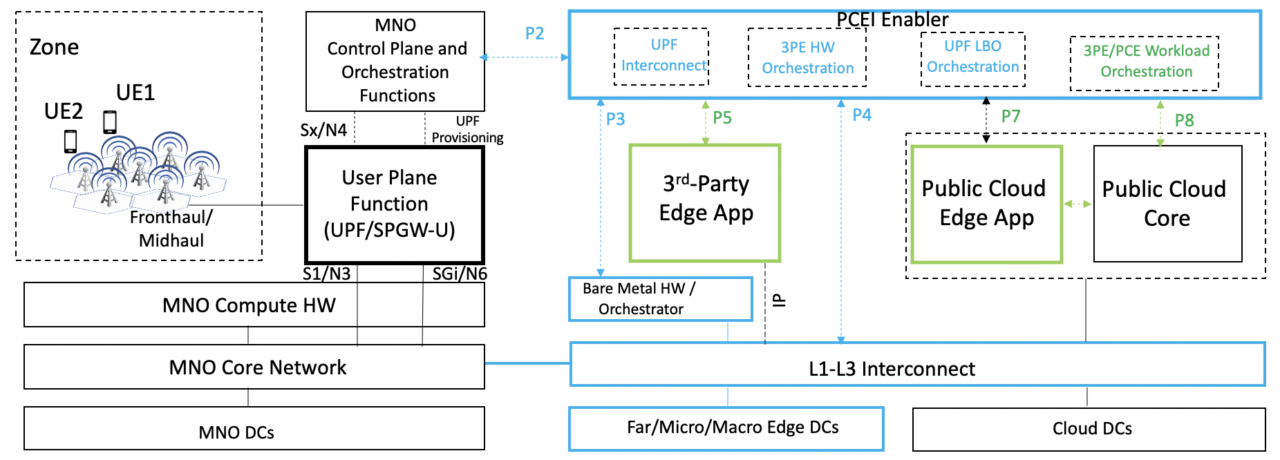
Figure 7. UPF N6/SGi Interconnection to 3PE/PCE/PCC Scenario.
Below is an example call flow for the UPF N6/SGi interconnection:
Figure 8. PCEI Facilitated UPF Interconnection on N6/SGi Call Flow.
UPF Placement Scenario
Assumptions:
- MNO supports CUPS (5G NSA) and/or UPF (5G SA).
- MNO may request UPF Placement / Metro, and 3PE/PCE Access / Metro, via APIs (on P2)
- Bare Metal Orchestration Provider and Interconnect Provider expose Data Center Location / Metro to PCEI Enabler via APIs (on P3 and P4)
- 3PE and PCE providers expose Data Center Location / Metro to PCEI Enabler via APIs (on P5 and P8/P7)
- PCEI Enabler may request Bare Metal Orchestration for Distributed UPF via APIs (on P3)
- PCEI Enabler may request Bare Metal Orchestration for 3PE via APIs (on P3)
- PCEI Enabler may request Interconnect for Distributed UPF N3/S1 and N6/SGi traffic (L2/L3) via APIs (on P4)
- PCEI Enabler may expose UPF management access to MNO
- MNO may provision the Distributed UPF over management access
- PCEI Enabler may provision UPF connectivity and LBO configuration (based on the UPF provisioning model) over P2’ using appropriate protocols
- PCEI Enabler may request PCC/PCE and/or 3PE Controller to instantiate workload instances for LBO processing via APIs (on P8/P5)
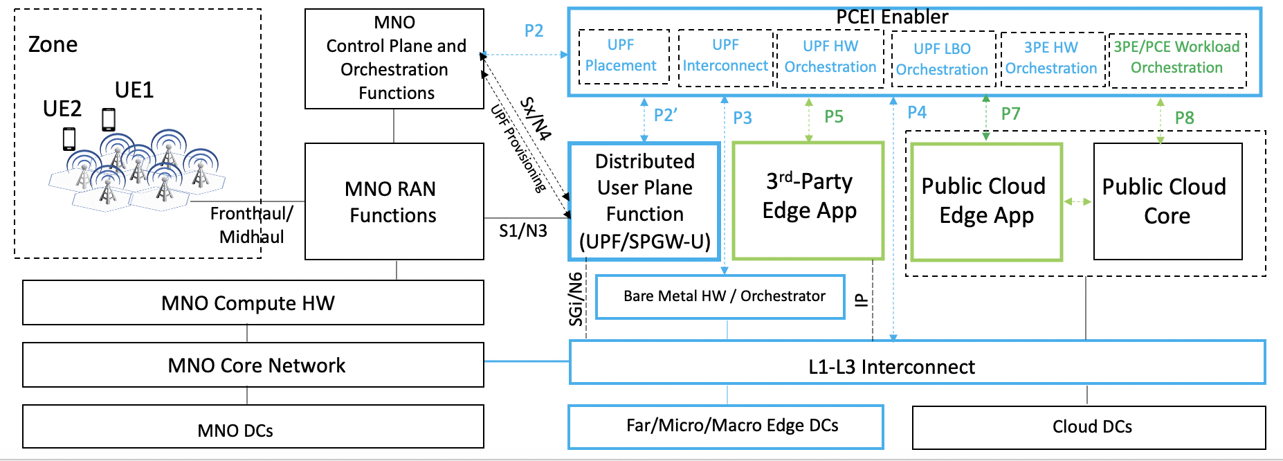
Figure 9. UPF Distribution/Placement and N3/S1 Interconnection to MNO, N6/SGi Interconnection to 3PE/PCE/PCC Scenario.
UPF Placement, Interconnection and Local Break-Out Options
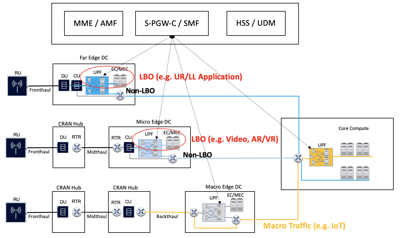
Figure 9. User Plane Function Distribution and Traffic Local Break-Out.
UPF Distribution:PCEI Facilitated Local-Break Out Orchestration(According to the procedure of 3GPP TS 29.522, public cloud application subscribe to NEF to set up the traffic route)
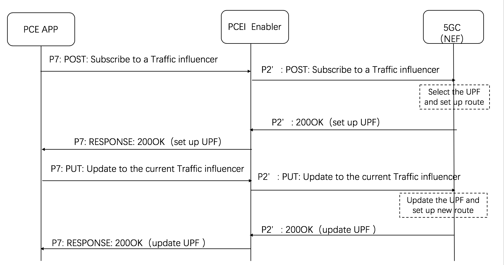
Figure 10. PCEI Facilitated Local Break-Out call flow.
the body of the HTTP POST message may include the AF Service Identifier, external Group Identifier, external Identifier, any UE Indication, the UE IP address, GPSI, DNN, S-NSSAI, Application Identifier or traffic filtering information, Subscribed Event, Notification destination address, a list of geographic zone identifier(s), AF Transaction Identifier, a list of DNAI(s), routing profile ID(s) or N6 traffic routing information, Indication of application relocation possibility, type of notifications, Temporal, spatial validity conditions, and if the URLLC feature is supported, Indication of AF acknowledgement to be expected and/or Indication of UE IP address preservation.
Local Breakout Orchestration with L1-L3 Interconnection coordination:
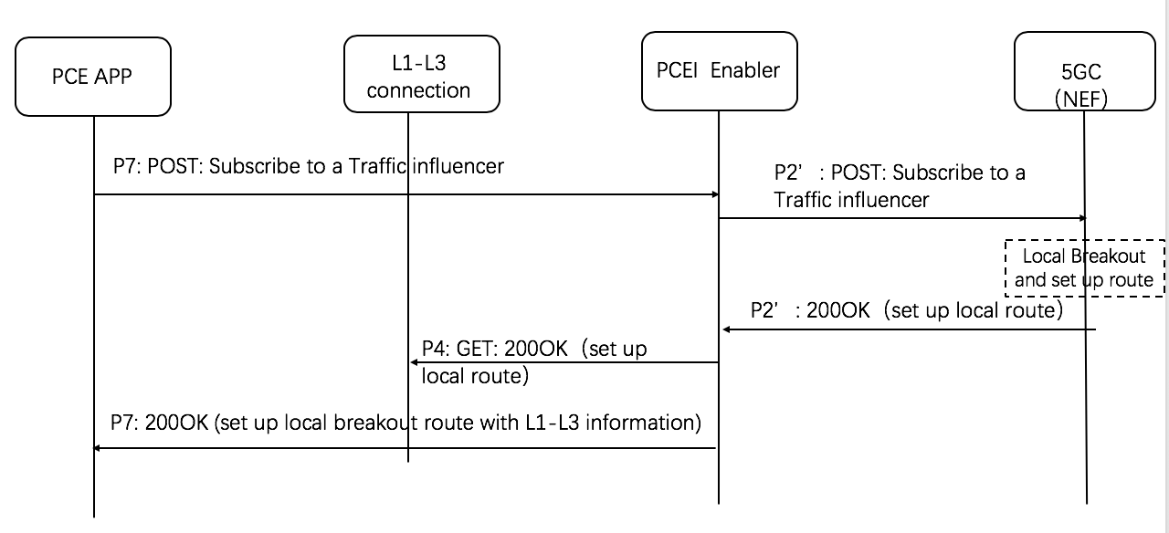
Figure 11. PCEI Facilitated Local Break-Out with L1-L3 Interconnection Coordination call flow.
Location Services (LS)
This use case targets obtaining geographic location of a specific UE provided by the 4G/5G network, identification of UEs within a geographical area as well as facilitation of server-side application workload distribution based on UE and infrastructure resource location.
Assumptions:
- MNO provides a Location Service (LS) compliant with OMA Zonal Presence API (OMA-TS-REST_NetAPI_ZonalPresence)
- MNO may expose the Location Service via the Network Exposure Function (NEF)
- A Public Cloud Edge (PCE) instance is associated with a Zone (collection of Access Points such as small cells) provided by an MNO
- A 3rd-Party Edge (3PE) instance is associated with a Zone (collection of Access Points such as small cells) provided by an MNO
- An application/workload in the PCE requires Location Information (e.g. coordinates of the Access Point) for the UE/subscriber
- An application/workload in the 3PE requires Location Information (e.g. coordinates of the Access Point) for the UE/subscriber
- PCEI Enabler facilitates Zonal Presence API Request/Response routing between PCE and the MNO LS and between the 3PE and the MNO LS

Figure 12. Location Services facilitated by PCEI.
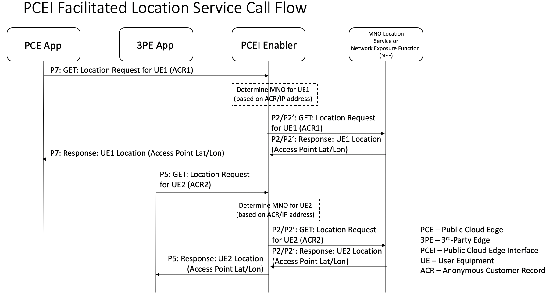
Figure 13. Location Services facilitated by PCEI.
Acknowledgements
Please add your names here