Blueprint Overview/Introduction
The Smart Data Transaction for CPS (Cyber-Physical Systems) Blueprint implements methods to adapt the edge network, possibly dynamically, to reduce pressure on network bandwidth and expand the potential range of the edge network's reach while reducing power consumption. The two main features of the blueprint are data sharing between edge nodes and the addition of support or low-power radio connections to sensors.
Use Cases
Below are some sample use cases which could benefit from the approaches implemented in this blueprint.
Interactive Live Sports/Music
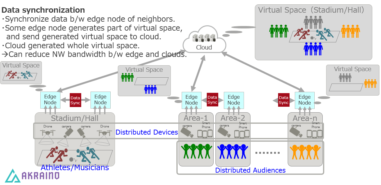
In a live event featuring audiences in multiple remote spaces, data can be combined by sharing between groups of edge nodes and sensors in each physical space. The combined data, such as video and audio feeds, can be integrated to provide a shared experience in a 3D virtual space to all audiences while reducing overall network bandwidth usage.
Agriculture/Infrastructure Monitoring
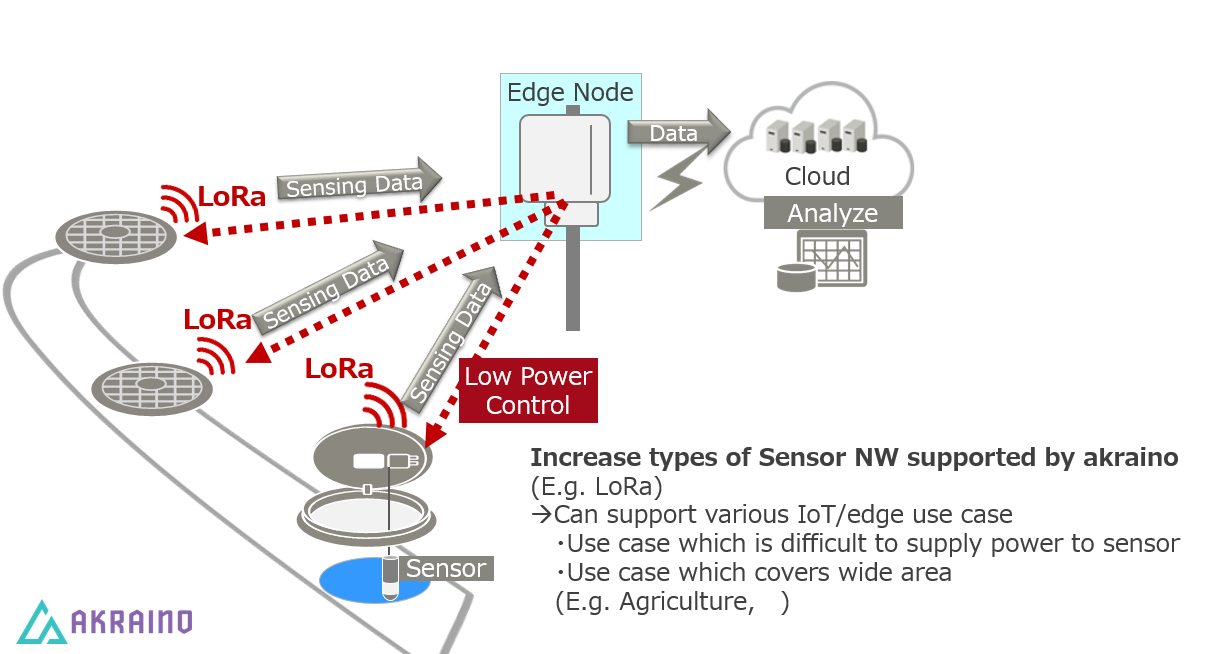
Widely separated sensor nodes can benefit from low-power radio connectivity to edge nodes, and edge nodes can react in real time to events in neighboring areas. The illustration below shows a storm drain monitoring application where, for example, sudden changes in water level can be used to trigger increased sampling rate in nearby sensors.
Where on the Edge
The blueprint is mainly focused on interactions between groups of smart edge nodes or gateways and sensors which can be grouped, either by physical location or by some other shared characteristics. The blueprint applies to situations where a large amount of data is generated from large numbers of sensor nodes, and which can benefit from localized integration and analysis of this data. Some such situations are described in the use cases above.
Business Drivers
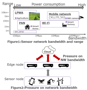
Cyber-physical systems (CPS), which combine sensor networks with computing to monitor and control the physical environment are becoming more popular each day. The bandwidth of the sensor network depends on use cases. Large amounts of data from large numbers of sensor nodes will put pressure on the available network bandwidth between the edge and the cloud. Therefore, we need to have a means to optimize bandwidth utilization according to use cases. This blueprint propose a solution for network bandwidth optimization through data sharing at the edge, also enabling a more responsive and smarter total system.
Overall Architecture
The diagram below shows the overall architecture of this blueprint. The colored components represent customizations or new implementations added for this blueprint. The details of the edge node and inter-edge data sharing are further illustrated below.
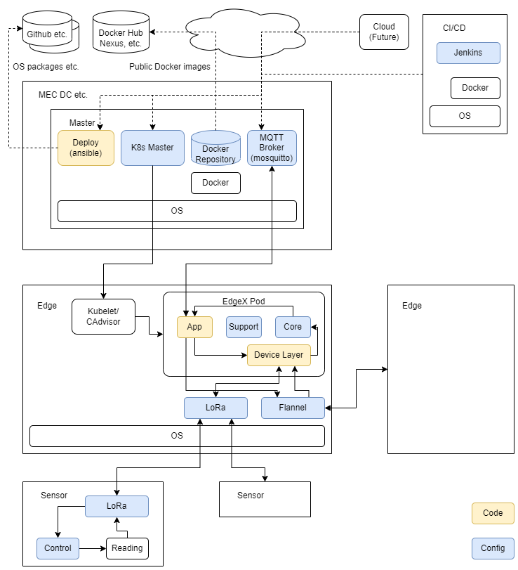
The Smart Data Transaction for CPS blueprint consists of the following types of node roles.
- CI/CD: Runs Jenkins to pull source and scripts, build components and run tests.
- Deploy: Runs scripts (mainly Ansible playbooks) to install components on master and edge nodes.
- Master: Runs the Kubernetes controller for orchestrating the edge nodes, a local docker registry providing container images for the edge nodes, and mosquitto (MQTT broker) for collecting data from edge nodes and sending commands to them.
- Edge: Collects sensor data, performs edge processing, and forwards data to the MQTT broker on the master node.
- Sensor: May be a smart sensor or a device containing sensor hardware and a communications device (e.g. LoRa) so that sensing data can be collected remotely by the edge nodes.
Some of the node roles can be combined on a single piece of hardware. For example, the "deploy" and "master" nodes can be the same server in practice.
The diagram below shows the details of the edge node. The edge node runs an instance of the EdgeX Foundry microservices stack. The EdgeX Foundry stack is instantiated on multiple edge nodes using Kubernetes from the master node.
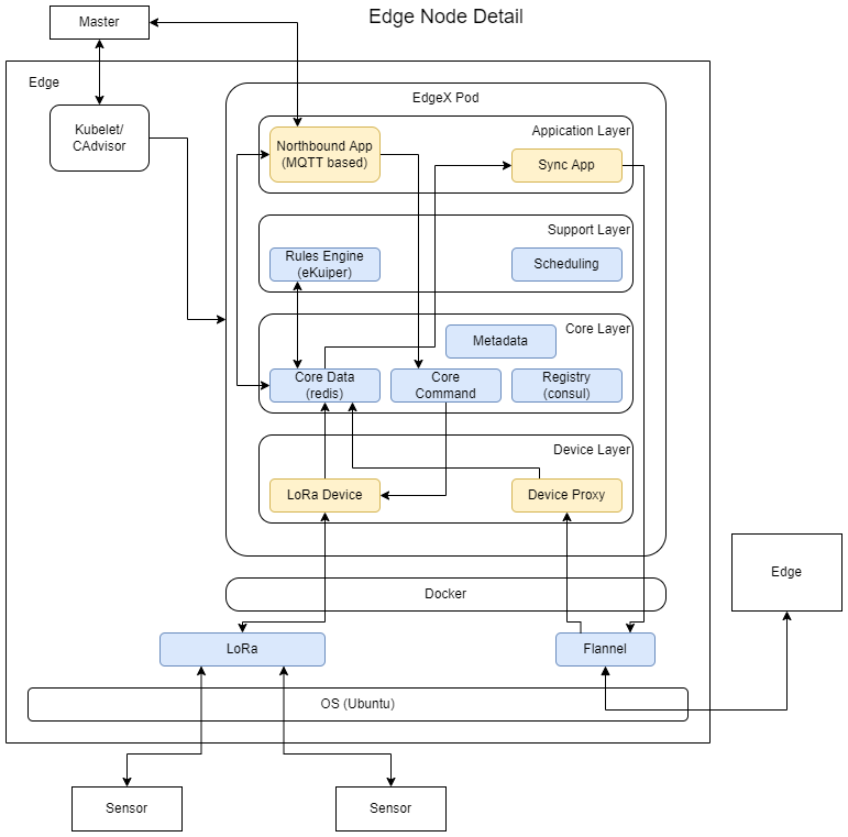
The new LoRa device service can provide low-power radio connectivity to remote sensor nodes from the edge nodes. The device proxy service and synchronization application allow edge nodes to share data.
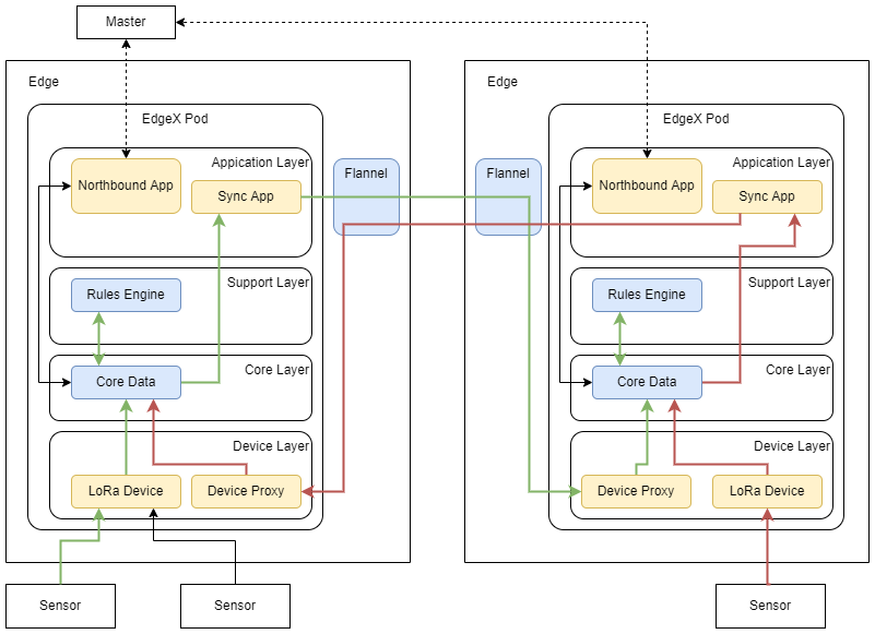
The diagram below illustrates the architecture for data sharing between two edge nodes. (The green and red lines show flows of data originating on the left and right nodes respectively.)
Platform Architecture
<Hardware components should be specified with model numbers, part numbers etc>
Software Platform Architecture
<Software components with version/release numbers >
<EDGE Interface>
<ETSI MEC Interaction>
APIs
APIs with reference to Architecture and Modules
High Level definition of APIs are stated here, assuming Full definition APIs are in the API documentation
Hardware and Software Management
Licensing
GNU/common license